6121 Baker Road, Suite 108 Minnetonka, MN 55345 Phone (952) 933-6190 Fax (952) 933-6223 1-800-274-4284 www.chtechnology.com Thank you for downloading this document from C&H Technology, Inc. Please contact the C&H Technology team for the following questions - Technical Application Assembly Availability Pricing Phone – 1-800-274-4284 E-Mail – sales@chtechnology.com www.chtechnology.com - SPECIALISTS IN POWER ELECTRONIC COMPONENTS AND ASSEMBLIES - www.chtechnology.
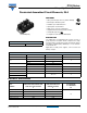
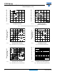
P100 Series Vishay High Power Products Passivated Assembled Circuit Elements, 25 A FEATURES • Glass passivated junctions for greater reliability • Electrically isolated base plate • Available up to 1200 VRRM/VDRM • High dynamic characteristics • Wide choice of circuit configurations • Simplified mechanical design and assembly • UL E78996 approved PACE-PAK (D-19) • Compliant to RoHS directive 2002/95/EC DESCRIPTION PRODUCT SUMMARY IO 25 A The P100 series of integrated power circuits consists of power th
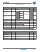
P100 Series Vishay High Power Products Passivated Assembled Circuit Elements, 25 A ON-STATE CONDUCTION PARAMETER Maximum DC output current at case temperature SYMBOL IO TEST CONDITIONS ITSM, IFSM t = 8.3 ms t = 10 ms I2t t = 8.3 ms t = 10 ms t = 8.3 ms Maximum I2√t for fusing Maximum value of threshold voltage I2√t VT(TO) Maximum level value of on-state slope resistance rt1 25 A 85 °C 357 No voltage reapplied 375 A t = 10 ms t = 8.
P100 Series Passivated Assembled Circuit Elements, 25 A Vishay High Power Products TRIGGERING PARAMETER SYMBOL Maximum peak gate power Maximum average gate power Maximum peak gate current Maximum peak negative gate voltage Maximum gate voltage required to trigger TEST CONDITIONS 8 PG(AV) 2 UNITS W IGM 2 A -VGM 10 V VGT TJ = - 40 °C 3 TJ = 25 °C 2 TJ = 125 °C IGT Maximum gate voltage that will not trigger VGD Maximum gate current that will not trigger IGD V 1 Anode supply = 6 V re
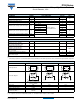
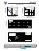
P100 Series Vishay High Power Products Passivated Assembled Circuit Elements, 25 A 60 + Maximum Total Power Loss (W) Maximum Total Power Loss (W) 60 ~ 50 40 180° (sine) 30 20 10 TJ = 125 °C = /W 15 K/ W 3K /W 30 -Δ R 5 K/ W 20 7 K/W 10 10 K/W 0 0 5 10 15 20 0 25 25 50 75 100 125 Maximum Allowable Ambient Temperature (°C) Fig.
P100 Series Passivated Assembled Circuit Elements, 25 A 400 350 At any rated load condition and with rated VRRM applied following surge. Initial TJ = 125 °C at 60 Hz 0.0083 s at 50 Hz 0.0100 s 300 Maximum non-repetitive surge current versus pulse train duration. Control of conduction may not be maintained.
Legal Disclaimer Notice Vishay Disclaimer All product specifications and data are subject to change without notice. Vishay Intertechnology, Inc., its affiliates, agents, and employees, and all persons acting on its or their behalf (collectively, “Vishay”), disclaim any and all liability for any errors, inaccuracies or incompleteness contained herein or in any other disclosure relating to any product.