
User guide


www.vishay.com For technical questions, contact: diodes-tech@vishay.com
Document Number: 94534
2 Revision: 15-Oct-08
MBR20T100CT
Vishay High Power Products
High Performance
Schottky Generation 5.0,
2 x 10 A
Note
(1)
Pulse width < 300 µs, duty cycle < 2 %
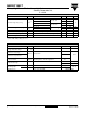
ELECTRICAL SPECIFICATIONS
PARAMETER SYMBOL TEST CONDITIONS TYP. MAX. UNITS
Forward voltage drop per leg V
FM
(1)
10 A
T
J
= 25 °C
-0.79
V
20 A - 0.88
10 A
T
J
= 125 °C
-0.68
20 A - 0.80
Reverse leakage current per leg I
RM
(1)
T
J
= 25 °C
V
R
= Rated V
R
- 100 µA
T
J
= 125 °C - 4 mA
Junction capacitance per leg C
T
V
R
= 5 V
DC
(test signal range 100 kHz to 1 MHz) 25 °C 400 - pF
Series inductance per leg L
S
Measured lead to lead 5 mm from package body 8.0 - nH
Maximum voltage rate of change dV/dt Rated V
R
- 10 000 V/µs
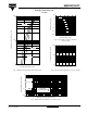
THERMAL - MECHANICAL SPECIFICATIONS
PARAMETER SYMBOL TEST CONDITIONS VALUES UNITS
Maximum junction and
storage temperature range
T
J
, T
Stg
- 55 to 175 °C
Maximum thermal resistance,
junction to case per leg
R
thJC
DC operation
2
°C/W
Maximum thermal resistance,
junction to case per device
1
Typical thermal resistance,
case to heatsink
R
thCS
Mounting surface, smooth and greased 0.5
Approximate weight
2g
0.07 oz.
Mounting torque
minimum 6 (5)
kgf · cm
(lbf · in)
maximum 12 (10)
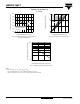
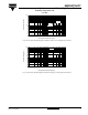
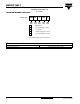
Marking device Case style TO-220AB MBR20T100CT