
User guide


Document Number: 94534 For technical questions, contact: diodes-tech@vishay.com
www.vishay.com
Revision: 15-Oct-08 1
High Performance
Schottky Generation 5.0, 2 x 10 A
MBR20T100CT
Vishay High Power Products
FEATURES
• 175 °C high performance Schottky diode
• Very low forward voltage drop
• Extremely low reverse leakage
• Optimized V
F
vs. I
R
trade off for high efficiency
• Increased ruggedness for reverse avalanche capability
• RBSOA available
• Negligible switching losses
• Submicron trench technology
• Full lead (Pb)-free and RoHS compliant devices
• Designed and qualified for industrial level
APPLICATIONS
• High efficiency SMPS
• Automotive
• High frequency switching
• Output rectification
• Reverse battery protection
• Freewheeling
• Dc-to-dc systems
• Increased power density systems
PRODUCT SUMMARY
I
F(AV)
2 x 10 A
V
R
100 V
V
F
at 10 A at 125 °C 0.68 V
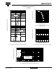
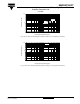
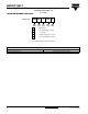
TO-220AB
Anode
13
2
Base
common
cathode
2
Common
cathode
Anode
MAJOR RATINGS AND CHARACTERISTICS
SYMBOL CHARACTERISTICS VALUES UNITS
V
RRM
100
V
V
F
10 Apk, T
J
= 125 °C (typical, per leg) 0.62
T
J
Range - 55 to 175 °C
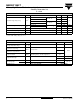
VOLTAGE RATINGS
PARAMETER SYMBOL TEST CONDITIONS MBR20T100CT UNITS
Maximum DC reverse voltage V
R
T
J
= 25 °C 100 V
ABSOLUTE MAXIMUM RATINGS
PARAMETER SYMBOL TEST CONDITIONS VALUES UNITS
Maximum average
forward current
per leg
I
F(AV)
50 % duty cycle at T
C
= 159 °C, rectangular waveform
10
A
per device 20
Maximum peak one cycle
non-repetitive surge current per leg
I
FSM
5 µs sine or 3 µs rect. pulse
Following any rated load
condition and with rated
V
RRM
applied
850
A
10 ms sine or 6 ms rect. pulse 200
Non-repetitive avalanche energy per leg E
AS
T
J
= 25 °C, I
AS
= 3 A, L = 12 mH 54 mJ
Repetitive avalanche current per leg I
AR
Limited by frequency of operation and time pulse duration so
that T
J
< T
J
max. I
AS
at T
J
max. as a function of time pulse
See fig. 8
I
AS
at
T
J
max.
A