
Instruction Manual


Document Number: 50051 For technical questions, contact: sfer@vishay.com
www.vishay.com
Revision: 16-Oct-08 3
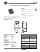
LTO 100
Power Resistor Thick Film Technology
Vishay Sfernice
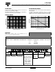
OVERLOADS
In any case the applied voltage must be lower than the
maximum overload voltage of 560 V.
The values indicated on the graph below are applicable to
resistors in air or mounted onto a heatsink.
MARKING
Model, style, resistance value (in Ω), tolerance (in %),
manufacturing date, VISHAY trademark.
POWER RATING CHART
The temperature of the case should be maintained within the
limits specified.
To improve the thermal conductivity, surfaces in contact
should be coated with a silicone grease and the torque
applied on the screw for tightening should be around 1 Nm.
10
-6
10
-5
10
-4
10
-3
10
-2
ENERGY IN JOULES
OVERLOAD DURATION IN s
ENER GY CURVE
0.01
0.1
1
10
PACKA GI NG
Tube of 30 units
0 20 40 60 80 100 120 140 160 175
100
75
50
25
0
% RATED POWER
HEATSINK TEMPERATURE IN °C
ORDERING INFORMATION
LTO 100 F 2.7 kΩ ± 1 % xxx TU30 e3
MODEL STYLE CONNECTIONS RESISTANCE VALUE TOLERANCE
± 1 %
± 2 %
± 5 %
± 10 %
CUSTOM DESIGN
Optional
on request:
Special TCR,
shape etc.
PACKAGING LEAD (Pb)-FREE
GLOBAL PART NUMBER INFORMATION
GLOBAL
MODEL
SIZE LEADS OHMIC VALUE TOLERANCE PACKAGING
LEAD (Pb)-FREE
LTO 100 F = Radial leads The firts four digits are
significant figures and the
last digit specifies the
number of zeros to follow.
R designates decimal point.
48R70 = 48.7 Ω
48701 = 48 700 Ω
10002 = 100 000 Ω
R0100 = 0.01 Ω
R4700 = 0.47 Ω
27000 = 2700 Ω = 2K7 Ω
F = 1 %
G = 2 %
J = 5 %
K = 10 %
T = Tube
Tube 30 pieces
E3 = Pure tin
100F270 0 T 3T OL 0JE