
Instruction Manual

Document Number: 94049 For technical questions, contact: ind-modules@vishay.com
www.vishay.com
Revision: 04-Aug-08 1
HEXFRED
®
Ultrafast Soft Recovery Diode, 60 A
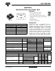
HFA120FA60P
Vishay High Power Products
FEATURES
• Fast recovery time characteristic
• Electrically isolated base plate
• Large creepage distance between terminal
• Simplified mechanical designs, rapid assembly
• UL pending
• Totally lead (Pb)-free
• Designed for industrial level
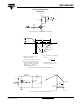
DESCRIPTION
This SOT-227 modules with HEXFRED
®
rectifier are
available in two basic configurations. They are the
antiparallel and the parallel configurations. The antiparallel
configuration (HFA120EA60) is used for simple series
rectifier and high voltage application. The parallel
configuration (HFA120FA60) is used for simple parallel
rectifier and high current application. The semiconductor in
the SOT-227 package is isolated from the copper base plate,
allowing for common heatsinks and compact assemblies to
be built. These modules are intended for general
applications such as power supplies, battery chargers,
electronic welders, motor control, DC chopper, and inverters.
PRODUCT SUMMARY
V
R
600 V
V
F
(typical) at 125 °C 1.4 V
Q
rr
(typical) 270 nC
I
RRM
(typical) 7.0 A
t
rr
(typical) 65 ns
dI
(rec)M
/dt (typical) at 125 °C 270 A/µs
I
F(DC)
at T
C
40 A at 100 °C
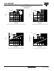
SOT-227
K2
K1
A1
A2
RoHS
COMPLIANT
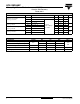
ABSOLUTE MAXIMUM RATINGS PER LEG
PARAMETER SYMBOL TEST CONDITIONS VALUES UNITS
Cathode to anode voltage V
R
600 V
Continuous forward current I
F
T
C
= 25 °C 75
A
T
C
= 100 °C 40
Single pulse forward current I
FSM
TBD
Maximum repetitive forward current I
FRM
180
RMS isolation voltage, any terminal to case V
ISOL
t = 1 minute 2500 V
Maximum power dissipation P
D
T
C
= 25 °C 180
W
T
C
= 100 °C 71
Operating junction and storage temperature range T
J
, T
Stg
- 55 to 150 °C
ELECTRICAL SPECIFICATIONS PER LEG (T
J
= 25 °C unless otherwise specified)
PARAMETER SYMBOL TEST CONDITIONS MIN. TYP. MAX. UNITS
Cathode to anode breakdown voltage V
BR
I
R
= 100 µA 600 - -
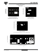
V
Maximum forward voltage V
FM
I
F
= 60 A
See fig. 1
-1.51.7
I
F
= 120 A - 1.9 2.1
I
F
= 60 A, T
J
= 125 °C - 1.4 1.6
Maximum reverse leakage current I
RM
V
R
= V
R
rated
See fig. 2
-2.520
µA
T
J
= 125 °C, V
R
= 0.8 x V
R
rated - 130 2000
Junction capacitance C
T
V
R
= 200 V See fig. 3 - 120 170 pF