
Owner manual

GT100DA60U
www.vishay.com
Vishay Semiconductors
Revision: 24-Oct-12
1
Document Number: 93185
For technical questions within your region: DiodesAmericas@vishay.com
, DiodesAsia@vishay.com, DiodesEurope@vishay.com
THIS DOCUMENT IS SUBJECT TO CHANGE WITHOUT NOTICE. THE PRODUCTS DESCRIBED HEREIN AND THIS DOCUMENT
ARE SUBJECT TO SPECIFIC DISCLAIMERS, SET FORTH AT www.vishay.com/doc?91000
Insulated Gate Bipolar Transistor
(Trench IGBT), 100 A
FEATURES
• Trench IGBT technology with positive
temperature coefficient
•Square RBSOA
• 3 μs short circuit capability
•FRED Pt
®
antiparallel diodes with ultrasoft
reverse recovery
•T
J
maximum = 175 °C
• Fully isolated package
• Very low internal inductance ( 5 nH typical)
• Industry standard outline
• Material categorization: For definitions of compliance
please see www.vishay.com/doc?99912
BENEFITS
• Designed for increased operating efficiency in power
conversion: UPS, SMPS, welding, induction heating
• Easy to assemble and parallel
• Direct mounting to heatsink
• Plug-in compatible with other SOT-227 packages
• Speed 4 kHz to 30 kHz
• Lower conduction losses and switching losses
• Low EMI, requires less snubbing
Note
(1)
Maximum continuous collector current must be limited to 100 A to do not exceed the maximum temperature of terminals
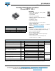
PRODUCT SUMMARY
V
CES
600 V
I
C
DC 100 A at 117 °C
V
CE(on)
typical at 100 A, 25 °C 1.72 V
I
F
DC 100 A at 25 °C
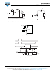
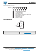
SOT-227
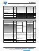
ABSOLUTE MAXIMUM RATINGS
PARAMETER SYMBOL TEST CONDITIONS MAX. UNITS
Collector to emitter voltage V
CES
600 V
Continuous collector current I
C
(1)
T
C
= 25 °C 184
A
T
C
= 80 °C 137
Pulsed collector current I
CM
350
Clamped inductive load current I
LM
350
Diode continuous forward current I
F
T
C
= 25 °C 100
T
C
= 80 °C 71
Peak diode forward current I
FSM
200
Gate to emitter voltage V
GE
± 20 V
Power dissipation, IGBT P
D
T
C
= 25 °C 577
W
T
C
= 117 °C 223
Power dissipation, diode P
D
T
C
= 25 °C 205
T
C
= 117 °C 79
Isolation voltage V
ISOL
Any terminal to case, t = 1 min 2500 V