
User guide
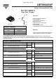

GB70NA60UF
Vishay Semiconductor Italy
2 Revision 13-Mar-09
R
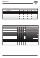
thCS
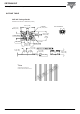
Case-to-Sink, flat, greased surface 0.05 °C/ W
T Mounting torque (M3 screw) 1.3 Nm
Wt Weight 30 g
Diode
R
thJC
Junction-to-Case, diode thermal resistance 0.45 °C/ W
IGBT
R
thJC
Junction-to-Case, IGBT thermal resistance 0.28 °C/ W
PARAMETERS MIN TYP MAX UNITS
THERMAL-MECHANICAL SPECIFICATION
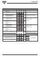
I
RM
Reverse leakage current 0.1 μA 600V
30 600V, T
J
= 125°C
V
FM
Forward voltage drop 2.2 V I
C
= 70A
1.7 I
C
= 70A, T
J
= 125°C
IGBT
BV
CES
Collector to emitter breakdown volt. 600 V V
GE
= 0V, I
C
= 500μA
ΔV
BR(CES)
/ΔT
J
Temp. coefficient of breakdown 0.85 V/°C V
GE
= 0V, I
C
= 1mA (25°C-125°C)
V
CE(on)
Collector to emitter voltage 1.72 V
GE
= 15V, I
C
= 35A
2.3 V V
GE
= 15V, I
C
= 70A
2.1 V
GE
= 15V, I
C
= 35A T
J
= 125°C
2.95 V
GE
= 15V, I
C
= 70A
V
GE(th)
Gate threshold voltage 4 V
CE
= V
GE
, I
C
= 500μA
ΔV
GE(th)
/ΔT
J
Temp.coeff. of threshold voltage 10 mV/°C V
CE
= V
GE
, I
C
= 1mA
I
CES
Zero gate voltage collector current 6 μAV
GE
= 0V, V
CE
= 600V
0.7 mA V
GE
= 0V, V
CE
= 600V, T
J
= 125°C
I
GES
Gate to emitter leakage current ± 200 nA V
GE
= ± 20V
PARAMETERS MIN TYP MAX UNITS TEST CONDITIONS
ELECTRICAL CHARACTERISTICS @ T
J
= 25°C (unless otherwise specified)