
Owner's manual
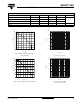
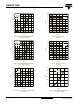
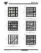
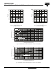
Table Of Contents
www.vishay.com For technical questions, contact: ind-modules@vishay.com
Document Number: 93653
6 Revision: 29-May-08
GB50YF120N
Vishay High Power Products
IGBT Fourpack Module, 50 A
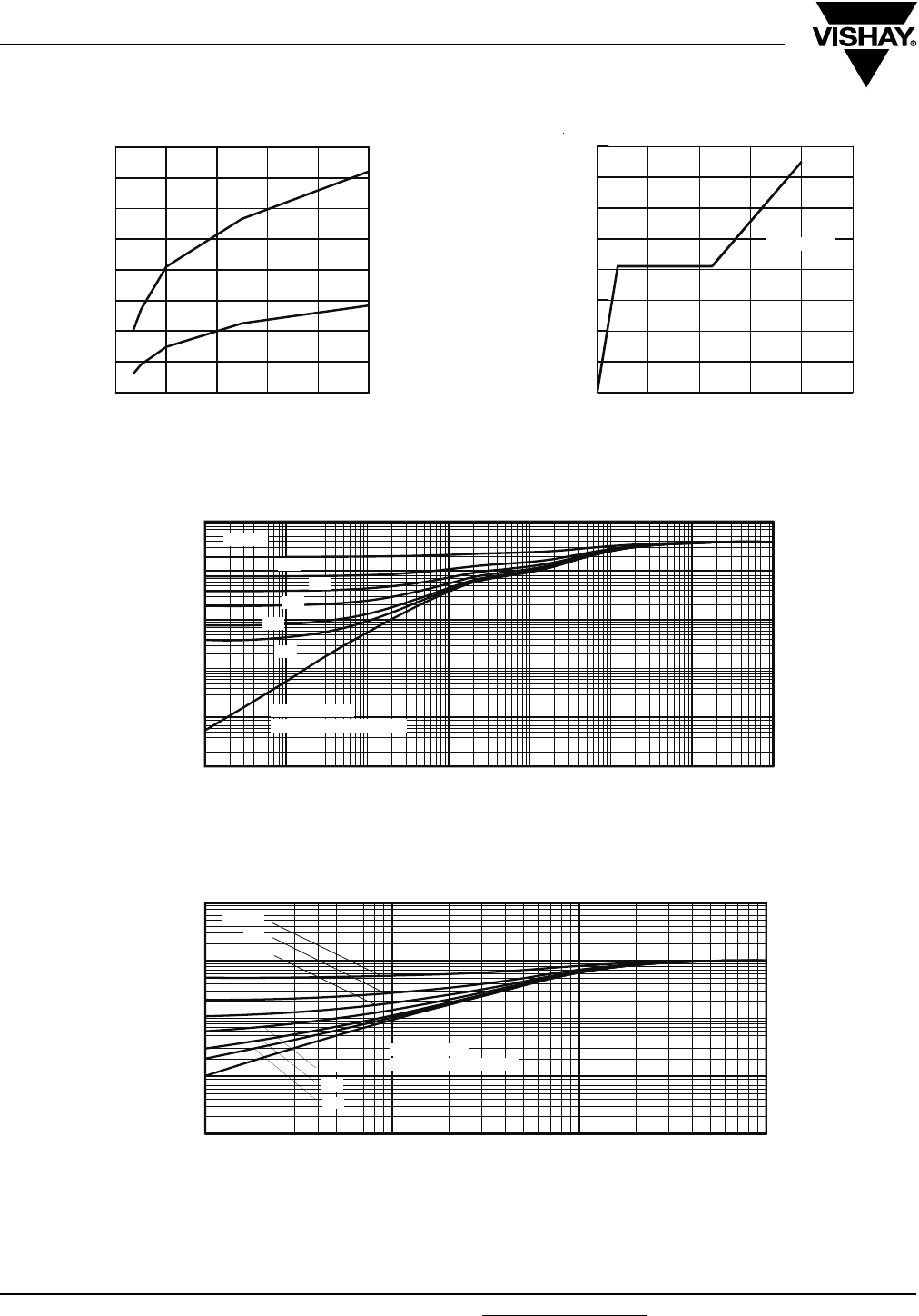
Fig. 17 - Typical Diode Q
rr
vs. dI
F
/dt
V
CC
= 600 V; I
F
= 50 A
Fig. 18 - Typical Gate Charge vs. V
GE
I
CE
= 5.0 A; L = 600 µH
Fig. 19 - Maximum Transient Thermal Impedance, Junction to Case (IGBT)
Fig. 20 - Maximum Transient Thermal Impedance, Junction to Case (DIODE)
0 20 40 60 80 100
0
200
400
600
800
1000
1200
1400
1600
125°C
25°C
dI
F/
dt (A/µs)
Q
RR
(nC)
0 100 200 300 400 500
0
2
4
6
8
10
12
14
16
typical value
Q
G
, Total Gate Charge (nC)
V
GE
(V)
1E-006 1E-005 0.0001 0.001 0.01 0.1 1 10
1E-005
0.0001
0.001
0.01
0.1
1
0.20
0.10
D = 0.50
0.01
0.02
0.05
SINGLE PULSE
( THERMAL RESPONSE )
t
1
, Rectangular Pulse Duration (sec)
Thermal Response (Z
thJC
)
1E-006 1E-005 0.0001 0.001
0.001
0.01
0.1
1
10
0.20
0.10
D = 0.50
0.01
0.02
0.05
SINGLE PULSE
( THERMAL RESPONSE )
t
1
, Rectangular Pulse Duration (sec)
Thermal Response (Z
thJC
)