6121 Baker Road, Suite 108 Minnetonka, MN 55345 Phone (952) 933-6190 Fax (952) 933-6223 (800) 274-4284 Thank you for downloading this document from C&H Technology, Inc. Please contact the C&H Technology team for the following questions - Technical Application Assembly Availability Pricing Phone – 1-800-274-4284 E-Mail – sales@chtechnology.com C & H TECHNOLOGY, INC. ● 6121 BAKER RD. SUITE 108 ● MINNETONKA, MINNESOTA 55345 ● 800-274-4284 ● 952-933-6190 ● FAX: 952-933-6223 ● WWW.CHTECHNOLOGY.
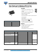
GB15XP120KTPbF Vishay Semiconductors Three Phase Inverter Module in MTP Package 1200 V NPT IGBT and HEXFRED® Diodes, 15 A FEATURES • Generation 5 NPT 1200 V IGBT technology • HEXFRED® diode with ultrasoft reverse recovery • Very low conduction and switching losses • Optional SMT thermistor (NTC) • Aluminum oxide DBC MTP • Very low stray inductance design for high speed operation • Short circuit 10 μs • Square RBSOA • Operating frequencies 8 kHz to 60 kHz • UL approved file E78996 PRODUCT SUMMARY • Compl
GB15XP120KTPbF Vishay Semiconductors Three Phase Inverter Module in MTP Package 1200 V NPT IGBT and HEXFRED® Diodes, 15 A ELECTRICAL SPECIFICATIONS (TJ = 25 °C unless otherwise specified) PARAMETER SYMBOL Collector to emitter breakdown voltage Temperature coefficient of V(BR)CES Collector to emitter voltage Gate threshold voltage V(BR)CES V(BR)CES/TJ VCE(on) VGE(th) TEST CONDITIONS MIN. TYP. MAX. 1200 - - V VGE = 0 V, IC = 1 mA - 1.
GB15XP120KTPbF Three Phase Inverter Module in MTP Package Vishay Semiconductors 1200 V NPT IGBT and HEXFRED® Diodes, 15 A THERMISTOR SPECIFICATIONS (T CODE ONLY) PARAMETER MIN. TYP. MAX. UNITS Resistance SYMBOL R0 (1) T0 = 25 °C TEST CONDITIONS - 30 - k Sensitivity index of the thermistor material (1)(2) T0 = 25 °C T1 = 85 °C - 4000 - K MIN. TYP. MAX. UNITS TJ - 40 - 150 TStg - 40 - 125 - - 1.1 - - 1.7 - 0.50 - - 0.
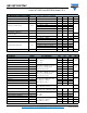
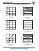
GB15XP120KTPbF Vishay Semiconductors Three Phase Inverter Module in MTP Package 1200 V NPT IGBT and HEXFRED® Diodes, 15 A 1000 20 tF Ice=7.5A Ice=15A Ice=30A tdOFF Swiching Time (ns) Vce (V) 15 10 5 100 tdON 10 tR 1 0 5 10 15 5 20 10 15 Vge (V) 25 30 Fig. 6 - Typical Switching Time vs. IC TJ = 125 °C, L = 500 μH, VCE = 600 V Rg = 10 ; VGE = 15 V Fig. 3 - Typical VCE vs. VGE TJ = 25 °C 4 20 ETOT Ice=7.
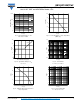
GB15XP120KTPbF Three Phase Inverter Module in MTP Package Vishay Semiconductors 1200 V NPT IGBT and HEXFRED® Diodes, 15 A 10000 120 Coes Ptot (W) Capacitance (pF) 90 Cies 1000 60 100 30 Cres 10 0 0 10 20 30 0 40 40 80 Tc (°C) Vce (V) 120 160 Fig. 12 - Power Dissipation vs. Case Temperature (IGBT only) Fig. 9 - Typical Capacitance vs. VCE VGE = 0 V; f = 1 MHz 16 100 600V 12 10 20 µs Ic (A) VGE (V) 100 µs 8 1 1 ms 4 10 ms 0.1 0 DC 0.
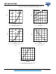
GB15XP120KTPbF Vishay Semiconductors Three Phase Inverter Module in MTP Package 1200 V NPT IGBT and HEXFRED® Diodes, 15 A 160 55 Rg=4.7Ω Tj = 25°C Tj = 125°C Irr (A) Ice (A) 120 Rg=10Ω 45 80 Rg=22Ω 35 25 Rg=47Ω 40 15 0 5 0 4 8 12 16 5 10 Vge (V) 15 20 25 30 35 If (A) Fig. 15 - Typical Transfer Characteristics VCE = 50 V; tp = 10 μs Fig. 17 - Typical Diode Irr vs.
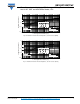
GB15XP120KTPbF Three Phase Inverter Module in MTP Package Vishay Semiconductors 1200 V NPT IGBT and HEXFRED® Diodes, 15 A Thermal Response (ZthJC) 10 1 0.5 0.3 0.1 0.1 R1 R1 0.05 τJ τ1 0.02 0.01 0.01 R2 R2 τ2 τ1 τ2 τ3 τ3 Ci= τi/Ri Ci i/Ri SINGLE PULSE (THERMAL RESPONSE) 0.001 1E-05 Ri (°C/W) τi (sec) 0.000547 0.196 0.025615 0.515 0.037176 0.389 R3 R3 1E-04 Notes: 1. Duty Factor D = t1/t2 2.
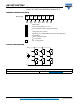
GB15XP120KTPbF Vishay Semiconductors Three Phase Inverter Module in MTP Package 1200 V NPT IGBT and HEXFRED® Diodes, 15 A ORDERING INFORMATION TABLE Device code GB 15 XP 120 K T PbF 1 2 3 4 5 6 7 1 - IGBT module 2 - Nominal current rating (15 = 15 A) 3 - Circuit configuration (XP = Three phase inverter) 4 - Voltage code (120 = 1200 V) 5 - Speed/type (K = Ultrafast IGBT/inverter motor drive application) 6 - Special option: None = No special option T = Thermistor - 7 PbF = L
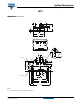
Outline Dimensions Vishay Semiconductors MTP Ø 1.1 20.5 12 ± 0.5 2.5 4 Ø5 3.5 DIMENSIONS in millimeters 31.8 33 2 8 7 6 5 4 3 1 13 9 10 11 1.8 12 8.1 1.2 ± 0.1 7.2 ± 0.1 7.8 ± 0.1 R2.6 (x 3) 5.7 ± 0.1 11.35 ± 0.1 5.4 ± 0.1 11.35 ± 0.1 27.5 3 ± 0.1 45° 8.7 ± 0.1 R5.8 (x 2) 8.5 ± 0.1 6 ± 0.1 3 ± 0.1 39.5 ± 0.1 44.5 48.7 1.3 63.5 ± 0.
Legal Disclaimer Notice www.vishay.com Vishay Disclaimer ALL PRODUCT, PRODUCT SPECIFICATIONS AND DATA ARE SUBJECT TO CHANGE WITHOUT NOTICE TO IMPROVE RELIABILITY, FUNCTION OR DESIGN OR OTHERWISE. Vishay Intertechnology, Inc., its affiliates, agents, and employees, and all persons acting on its or their behalf (collectively, “Vishay”), disclaim any and all liability for any errors, inaccuracies or incompleteness contained in any datasheet or in any other disclosure relating to any product.