
User guide

ER
Vishay ESTA
Document Number: 13013
Revision 04-Jan-02
www.vishay.com
7
TYPE ER
Capacitors offer unusually good electrical
characteristics, coupled with very small size.
The ER range of capacitors are manufactured using a
mixed dielectric material that consists of
polyester/polypropylene. The container is a rolled
seamed tinplate case that is hermetically sealed. The
construction is designed to prevent internal movement
when subjected to shock and vibration.
Note: The impregnant used is a non toxic highly refined,
purified and inhibited mineral oil.
APPLICATIONS
The ER range of capacitors are specifically designed for
DC applications.
• Audio coupling
• Pulse forming networks
• Oscillator circuits
• Arc and spark suppression
• RF by-pass
• Tuned filters
• Energy storage
• Integrating circuits
• Low and high pass filters
• High voltage smoothing
Capacitors required for AC applications and High
Discharge rates can also be designed from the ER
range.
Consult Vishay Electronic GmbH, Division Roederstein
ESTA and Hybrids for your specific requirements.
TEMPERATURE RANGE
Temperature range is – 55°C to + 85°C. The nominal
voltage rating is applicable from – 55°C to + 85°C.
Derating is required for higher operating temperatures.
TEMPERATURE COEFFICIENT
Capacitance will increase by 2% per 100°C
temperature change.
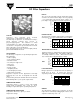
RIPPLE
The sum of the peak ripple voltage and the DC voltage
should not exceed the rated voltage. Refer to graph fig
1 for permissible peak-to-peak ripple voltage as a
percentage of rated voltage for various frequencies.
POWER FACTOR
The power factor is variable, and a function of temperature
and frequency. See fig 2. Nominal value <0.5% at 20°C.
DC Filter Capacitors
30
10
20
10 100 1000
%
R
I
P
P
L
E
FREQUENCY Hz
0
10000
10
5
10
3
10
4
50
100
150°
H
O
U
R
S
RATED VOLTAGE
FIG 1
FIG 4
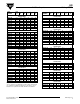
DIELECTRIC RESISTANCE
(Parallel resistance) is indicated by the graph of insulance
(MΩ x µF) vs temperature fig 3. The insulance (MΩ x µF)
is nominally 10000s at + 20°C. (Measurements taken
after 1 minute with an applied
voltage of 500V).
LIFE EXPECTANCY
ER type capacitors are designed for a life exceptancy of
50000 hours at 65°C. To achieve the same life
expectancy at 85°C derate to 60% of rated voltage fig 4.
WEIGHT
The approximate weight in kg of capacitors in the ER
range can be estimated by multiplying the volume of the
capacitor container by 1.45* x 10
-6
.
10
4
10
2
10
3
040
80
M
E
G
O
H
M
S
x
M
F
D
INSULANCE VS TEMPERATURE
TYPICAL VALUES
- 40
FIG 3
2%
0%
1%
040
80
POWER FACTOR
vs
TEMPERATURE
- 20
at 20°C
50H
z
1kH
z
65
FIG 2