
User Manual

www.vishay.com For technical questions, contact: ind-modules@vishay.com
Document Number: 94483
2 Revision: 01-Sep-08
CPV362M4UPbF
Vishay High Power Products
IGBT SIP Module
(Fast IGBT)
Notes
(1)
Pulse width ≤ 80 µs; duty factor ≤ 0.1 %
(2)
Pulse width 5.0 µs, single shot
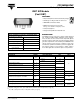
THERMAL AND MECHANICAL SPECIFICATIONS
PARAMETER SYMBOL TYP. MAX. UNITS
Junction to case, each IGBT, one IGBT in conduction R
thJC
(IGBT) - 5.5
°C/WJunction to case, each DIODE, one DIODE on conduction R
thJC
(DIODE) - 9.0
Case to sink, flat, greased surface R
thCS
(MODULE) 0.1 -
Weight of module
20 g
0.7 oz.
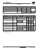
ELECTRICAL SPECIFICATIONS (T
J
= 25 °C unless otherwise noted)
PARAMETER SYMBOL TEST CONDITIONS MIN. TYP. MAX. UNITS
Collector to emitter breakdown voltage V
(VB)CES
(1)
V
GE
= 0 V, I
C
= 250 µA 600 - - V
Temperature coefficient of
breakdown voltage
ΔV
(BR)CES
/ΔT
J
V
GE
= 0 V, I
C
= 1 mA - 0.63 - V/°C
Collector to emitter saturation voltage V
CE(on)
I
C
= 3.9 A
V
GE
= 15 V
See fig. 2, 5
- 1.70 2.2
V
I
C
= 7.2 A - 1.95 -
I
C
= 3.9 A, T
J
= 150 °C - 1.70 -
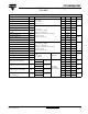
Gate threshold voltage V
GE(th)
V
CE
= V
GE
, I
C
= 250 µA
3.0 - 6.0
Temperature coefficient of
threshold voltage
ΔV
GE(th)
/ΔT
J
-- 11-mV/°C
Forward transconductance g
fe
(2)
V
CE
= 100 V, I
C
= 6.5 A 1.4 4.3 - S
Zero gate voltage collector current I
CES
V
GE
= 0 V, V
CE
= 600 V - - 250
µA
V
GE
= 0 V, V
CE
= 600 V, T
J
= 150 °C - - 2500
Diode forward voltage drop V
FM
I
C
= 8.0 A
See fig. 13
-1.41.7
V
I
C
= 8.0 A, T
J
= 150 °C - 1.3 1.6
Gate to emittler leakage current I
GES
V
GE
= ± 20 V - - ± 100 nA