
User Manual
Powerex, Inc., 173 Pavilion Lane, Youngwood, Pennsylvania 15697 (724) 925-7272
www.pwrx.com
Dual IGBTMOD™
NX-S Series Module
600 Amperes/1200 Volts
CM600DXL-24S
106/11 Rev. 3
Description:
Powerex IGBTMOD™ Modules
are designed for use in switching
applications. Each module
consists of two IGBT Transistors
in a half-bridge configuration with
each transistor having a reverse-
connected super-fast recovery
free-wheel diode. All components
and interconnects are isolated from
the heat sinking baseplate, offering
simplified system assembly and
thermal management.
Features:
£ Low Drive Power
£ Low V
CE(sat)
£
Discrete Super-Fast Recovery
Free-Wheel Diode
£ Isolated Baseplate for Easy
Heat Sinking
Applications:
£ AC Motor Control
£ Motion/Servo Control
£ Photovoltaic/Fuel Cell
Ordering Information:
Example: Select the complete
module number you desire from
the table below -i.e.
CM600DXL-24S is a 1200V
(V
CES
), 600 Ampere Dual
IGBTMOD™ Power Module.
Type Current Rating
V
CES
Amperes Volts (x 50)
CM 600 24
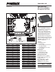
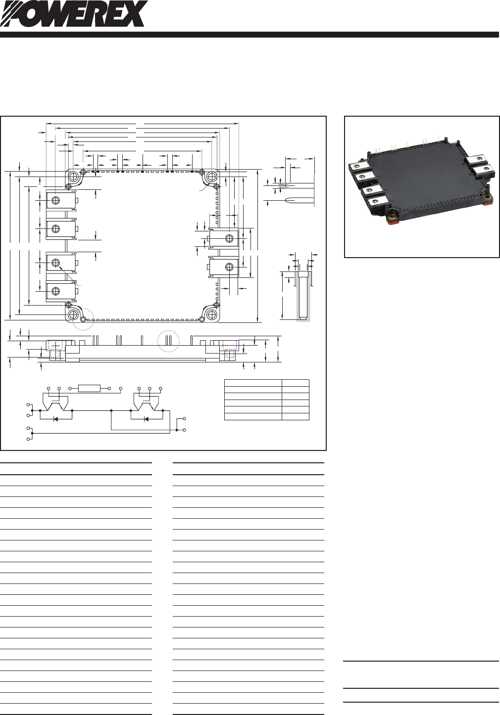
Outline Drawing and Circuit Diagram
Dimensions Inches Millimeters
A 5.98 152.0
B 5.39 137.0
C 4.79 121.7
D 4.61 117.2
E 4.33±0.02 110.0±0.5
F 3.72 94.5
G 0.6 15.14
H 0.26 6.5
J 0.53 13.5
K 0.14 3.6
L 0.3 7.75
M 0.016 4.05
N 1.53 39.0
P 0.86 22.0
Q 1.95 49.72
R 1.62 41.22
S 0.83 21.14
T 0.23 6.0
U 0.47 12.0
V 0.41 10.53
W M6 Metric M6
X 0.22 5.5 Dia.
Dimensions Inches Millimeters
Y 0.75 19.24
Z 0.86 22.0
AA 1.08 27.53
AB 0.14 3.5
AC 0.51 13.0
AD 0.19 3.0
AE 0.42 10.74
AF 0.67+0.04/-0.02 17.0+1.0/-0.5
AG 0.81 20.5
AH 0.29 7.4
AJ 0.05 1.2
AK 0.02 0.65
AL 0.04 1.15
AM 0.15 3.81
AN 0.5 12.5
AP 0.12 3.0
AQ 0.088 Dia. 2.25 Dia.
AR 0.102 Dia. 2.6 Dia.
AS 0.16 Dia. 4.3 Dia.
AT 0.67 16.9
AU 0.6 15.24
AV 0.75 19.05
Di1 Di2
Tr 1Tr2
Es1
(62)
G1
(61)
TH2
(57)
TH1
(56)
Th
Cs1
(52)
Es2
(47)
G2
(46)
Cs2
(42)
C1(1)
C1(2)
E2(3)
E2(4)
E1C2 (32)
E1C2 (33)
NTC
DETAIL "B"
A
B
C
D
E
F
G
J
K
L
L
K
Y
AAFED
Z
Z
AC
R
AB
AD
H
AC
AF
AG
U
T
P
QR
NC
S
M
AH
AJ
AN
AS
AR
AQ
AP
AM
AL
AK
DETAIL "B"
DETAIL "A"
W(6 PLACES)
X(4 PLACES)
DETAIL "A"
1
2
3
4
56789101112131415161718192021222324252627
63 62 61 60 59 58 57 56 55 54 53 52 51 50 49 48 47 46 45 44 43 42 41
28
29
30
31
32
33
37
38
39
34
35
36
40
AT
AE
V
AU AU AV AU
AM AM
AM
H
The tolerance of size between
terminals is assumed to ±0.4
Division of Dimension Tolerance
0.5 to 3 ±0.2
over 3 to 6 ±0.3
over 6 to 30 ±0.5
over 30 to 120 ±0.8
over 120 to 400 ±1.2
Tolerance Otherwise Specified (mm)