
User Manual


3
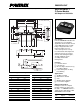
CM600DU-24F
Dual IGBTMOD™ F-Series Module
600 Amperes/1200 Volts
Powerex, Inc., 200 E. Hillis Street, Youngwood, Pennsylvania 15697-1800 (724) 925-7272
3
Dynamic Electrical Characteristics, T
j
= 25 °C unless otherwise specified
Characteristics Symbol Test Conditions Min. Typ. Max. Units
Input Capacitance C
ies
––230 nf
Output Capacitance C
oes
V
CE
= 10V, V
GE
= 0V – – 10 nf
Reverse Transfer Capacitance C
res
––6nf
Resistive Turn-on Delay Time t
d(on)
V
CC
= 600V, I
C
= 600A, – – 450 ns
Load Rise Time t
r
V
GE1
= V
GE2
= 15V, – – 200 ns
Switch Turn-off Delay Time t
d(off)
R
G
= 1.0⍀,––800 ns
Times Fall Time t
f
Inductive Load – – 300 ns
Diode Reverse Recovery Time* t
rr
Switching Operation – – 500 ns
Diode Reverse Recovery Charge* Q
rr
I
E
= 600A – 43.2 – µC
Thermal and Mechanical Characteristics, T
j
= 25 °C unless otherwise specified
Characteristics Symbol Test Conditions Min. Typ. Max. Units
Thermal Resistance, Junction to Case R
th(j-c)
QPer IGBT 1/2 Module, T
c
Reference – – 0.081 °C/W
Point per Outline Drawing
Thermal Resistance, Junction to Case R
th(j-c)
RPer FWDi 1/2 Module, T
c
Reference – – 0.11 °C/W
Point per Outline Drawing
Thermal Resistance R
th(j-c')
QPer IGBT 1/2 Module – – 0.032** °C/W
T
c
Reference Point Under Chips
Contact Thermal Resistance R
th(c-f)
Per Module, Thermal Grease Applied – 0.010 – °C/W
External Gate Resistance R
G
1.0 – 52 Ω
*Represents characteristics of the anti-parallel, emitter-to-collector free-wheel diode (FWDi).
**If you use this value, R
th(f-a)
should be measured just under the chips.