
Owner's manual
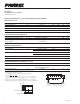

Powerex, Inc., 173 Pavilion Lane, Youngwood, Pennsylvania 15697 (724) 925-7272
www.pwrx.com
Six IGBTMOD™
NX-S Series Module
100 Amperes/1200 Volts
CM100TX-24S
107/11 Rev. 2
Description:
Powerex IGBTMOD™ Modules
are designed for use in switching
applications. Each module
consists of six IGBT Transistors in
a three phase bridge configuration
with each transistor having a
reverse-connected super-fast
recovery free-wheel diode. All
components and interconnects
are isolated from the heat sinking
baseplate, offering simplified
system assembly and thermal
management.
Features:
£ Low Drive Power
£ Low V
CE(sat)
£
Discrete Super-Fast Recovery
Free-Wheel Diode
£ Isolated Baseplate for Easy
Heat Sinking
Applications:
£ AC Motor Control
£ Motion/Servo Control
£ Photovoltaic/Fuel Cell
Ordering Information:
Example: Select the complete
module number you desire from
the table below -i.e.
CM100TX-24S is a 1200V (V
CES
),
100 Ampere Six IGBTMOD™ Pow-
er Module.
Type Current Rating
V
CES
Amperes Volts (x 50)
CM 100 24
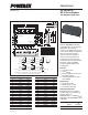
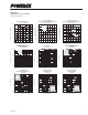
Outline Drawing and Circuit Diagram
Dimensions Inches Millimeters
A 4.79 121.7
B 2.44 62.0
C 0.51 13.0
D 4.49 114.05
E 4.33±0.02 110.0±0.5
F 3.9 99.0
G 3.72 94.5
H 0.59 15.0
J 0.96 24.52
K 0.15 3.81
L 0.45 11.43
M 0.6 15.24
N 0.22 Dia. 5.5 Dia.
P 2.13 54.2
Q 0.30 7.75
R 1.97±0.02 50.0±0.5
S 2.26 57.5
T 0.165 4.2
Dimensions Inches Millimeters
U 0.16 4.06
V 0.46 11.66
W 0.14 3.75
X 0.14 3.5
Y 0.03 0.8
Z 0.28 7.0
AA 0.81 20.5
AB 0.67 17.0
AC 0.03 0.65
AD 0.05 1.15
AE 0.29 7.4
AF 0.047 1.2
AG 0.49 12.5
AH 0.12 3.0
AJ 0.17 Dia. 4.3 Dia.
AK 0.102 Dia. 2.6 Dia.
AL 0.088 Dia. 2.25 Dia.
P(54~56)
G
WN(21)
N1(23~25)
Caution: Each (three) pin terminal of P/N/P1/N1/U/V/W is connected in the module,
however, all three pins should be used for external wiring.
G
WP(17)
E
WP(18)
G
VN(13)
G
VP(9)
E
VP(10)
G
UN(5)
G
UP(1)
E
UP(2)
EWN(22)EVN(14)EUN(6)
U(48~50) V(42~44) W(36~38)
N(59~61)
TH1
(31)
TH
2
(32)
P1(28~30)
DETAIL "B"
A
AA
P
D
E
F
G
K
K
K
K
K
KQ
K
L
V
W
Z
AH
C
AB
R B
N
(4 PLACES)
KKKKKK
U
X
K
K
K
K
L
K
K
K
K
LHLLLL
Y
S
DETAIL "A"
12345678910111213141516171819202122
53
54
55
56
57
58
59
60
61
30
29
28
27
26
25
24
23
52 51 50 49 48 47 46 45 44 43 42 41 40 39 38 37 36 35 34 33 32 31
JMMM
AC
K
AD
AF
AE
AG
AL
AH
T
AK
AJ
DETAIL "B"
DETAIL "A"
Tolerance Otherwise Specified (mm)
The tolerance of size between
terminals is assumed to ±0.4
Division of Dimension Tolerance
0.5 to 3 ±0.2
over 3 to 6 ±0.3
over 6 to 30 ±0.5
over 30 to 120 ±0.8
over 120 to 400 ±1.2