
User Manual
Powerex, Inc., 173 Pavilion Lane, Youngwood, Pennsylvania 15697 (724) 925-7272
www.pwrx.com
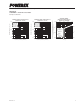
Six IGBTMOD™ + Brake
NX-S Series Module
100 Amperes/1200 Volts
CM100RX-24S
106/11 Rev. 2
Description:
Powerex IGBTMOD™ Modules
are designed for use in switching
applications. Each module
consists of six IGBT Transistors in
a three phase bridge configuration
and a seventh IGBT with free-
wheel diode for dynamic braking.
All components and interconnects
are isolated from the heat sinking
baseplate, offering simplified
system assembly and thermal
management.
Features:
£ Low Drive Power
£ Low V
CE(sat)
£
Discrete Super-Fast Recovery
Free-Wheel Diode
£ Isolated Baseplate for Easy
Heat Sinking
Applications:
£ AC Motor Control
£ Motion/Servo Control
£ Photovoltaic/Fuel Cell
Ordering Information:
Example: Select the complete
module number you desire from
the table below -i.e.
CM100RX-24S is a 1200V (V
CES
),
100 Ampere Six-IGBTMOD™ +
Brake Power Module.
Type Current Rating
V
CES
Amperes Volts (x 50)
CM 100 24
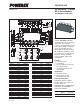
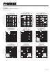
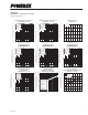
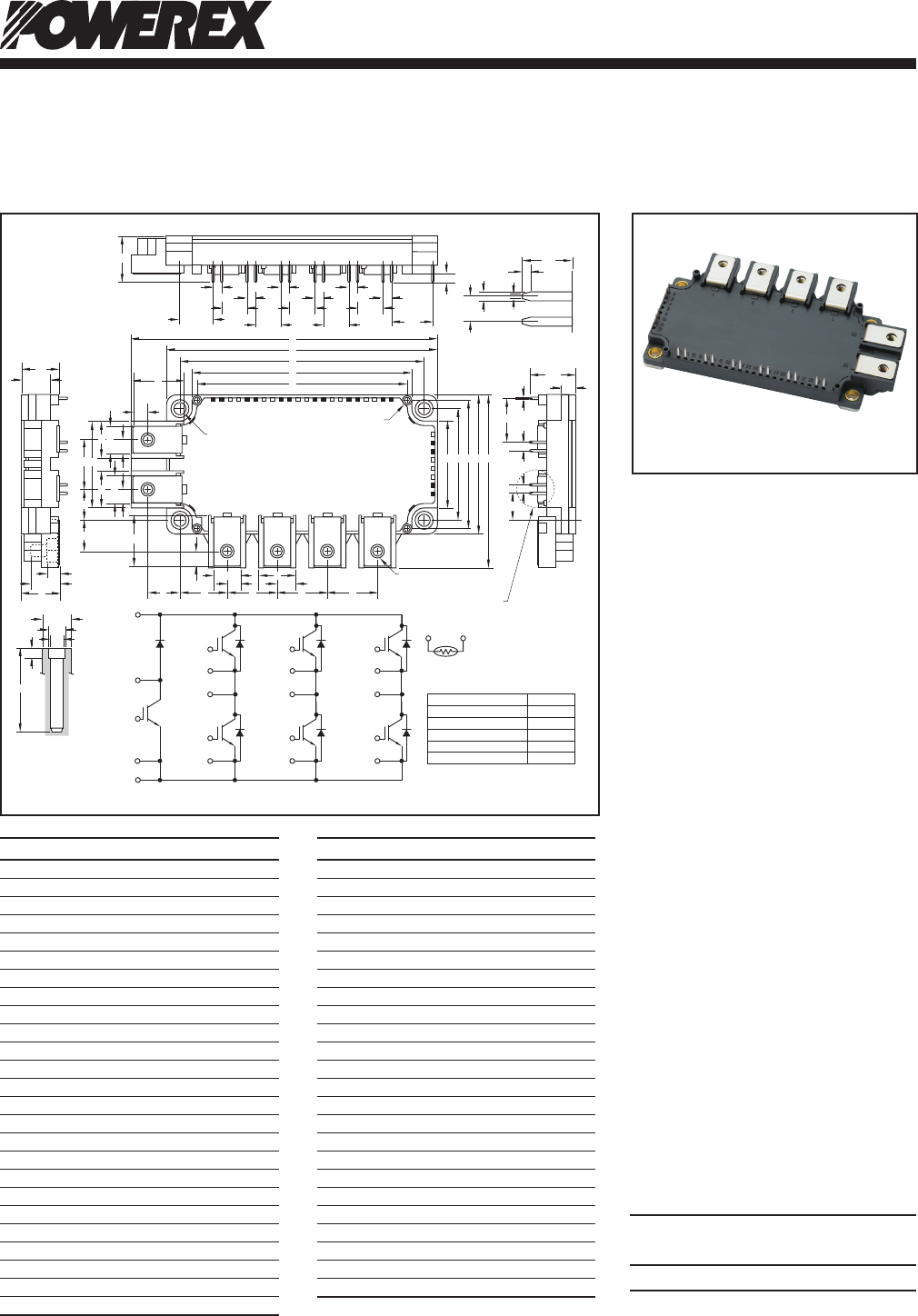
Outline Drawing and Circuit Diagram
Dimensions Inches Millimeters
A 5.39 136.9
B 3.03 77.1
C 0.67+0.04/-0.02 17.0+1.0/-0.5
D 4.79 121.7
E 4.33±0.02 110.0±0.5
F 3.89 99.0
G 3.72 94.5
H 0.83 21.14
J 0.37 6.5
K 2.44 62.0
L 2.26 57.5
M 1.97±0.02 50.0±0.5
N 1.53 39.0
P 0.24 6.0
Q 0.48 12.0
R 0.67 17.0
S 1.53 39.0
T 0.87 22.0
U 0.55 14.0
V 0.54 13.64
W 0.33 8.5
X 0.53 13.5
Y 0.81 20.71
Z 0.9 22.86
AA 0.22 Dia. 5.5 Dia.
Dimensions Inches Millimeters
AB M5 M5
AC 0.12 3.0
AD 0.51 13.0
AE 0.102 Dia. 2.6 Dia.
AF 0.21 5.4
AG 0.49 12.5
AH 0.81 20.5
AJ 0.088 Dia. 2.25 Dia.
AK 0.59 15.00
AL 0.15 3.81
AM 0.45 11.43
AN 0.14 3.5
AP 0.75 19.05
AQ 0.05 1.2
AR 0.03 0.8
AS 0.27 7.0
AT 0.77 19.68
AU 0.49 12.5
AV 0.60 15.24
AW 0.46 11.66
AX 0.04 1.15
AY 0.02 0.65
AZ 0.29 7.4
BA 0.17 Dia. 4.3 Dia.
P(35)
B(4)
G
WN(14)
G
WP(18)
E
WP(17)
G
VN(22)
G
VP(26)
E
VP(25)
G
UN(30)
EWN(13)EVN(21)EUN(29)
G
UP(34)
E
UP(33)
U(1) V(2) W(3)
GB(6)
N(36)
TH1
(11)
TH2
(10)
NTC
EB(5)
A
AH
AZ
AQ
QR
S
T
U
V
H
X Y Z Z
N M L K B
AN
AMAMAM
AM
AP
AM
AK
AL
AX
AY
AL
ALALAL
ALAL
Z
RQ
Q
R
D
E
F
G
H
J
P
P W
J
P
AA(4 PLACES)
DETAIL "B"
AB
(6 PLACES)
DETAIL "A"
34 33 32 31 30 29 28 27 26 25 24 23 22 21 20 19 18 17 16 15 14 13
12
35
36
1 2 3 4
11
10
9
8
7
6
5
DETAIL "B"
C
R
AH
AT
AW
AS
AR
AL
AL
AD
AF
AG
AU
BA
AE
AJ
AC
DETAIL "A"
Tolerance Otherwise Specified (mm)
The tolerance of size between
terminals is assumed to ±0.4
Division of Dimension Tolerance
0.5 to 3 ±0.2
over 3 to 6 ±0.3
over 6 to 30 ±0.5
over 30 to 120 ±0.8
over 120 to 400 ±1. 2