
Owner's manual
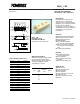

Powerex, Inc., Hillis Street, Youngwood, Pennsylvania 15697 (724) 925-7272 POW-R-BLOK
TM
www.pwrx.com Dual SCR Isolated Module
150 Amperes / Up to 1800 Volts
Revision Date: 04/28/2009
CD63__15B
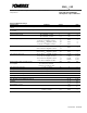
Electrical Characteristics, T
J
=25°C unless otherwise specified
Characteristics Symbol Test Conditions Min.
Max.
Units
Repetitive Peak Forward Leakage Current I
DRM
Up to 1800V, T
J
=125°C 50 mA
Repetitive Peak Reverse Leakage Current I
RRM
Up to 1800V, T
J
=125°C 50 mA
Peak On-State Voltage V
TM
I
TM
=500A 1.6 V
Threshold Voltage, Low-level
Slope Resistance, Low-level
V
(TO)1
r
T1
T
J
= 125°C, I = 16.7% x
π
I
T(AV)
to
π
I
T(AV)
0.85
1.5
V
mΩ
Minimum dV/dt dV/dt
Exponential to 2/3 V
DRM
T
j
=125°C, Gate Open
1000 V/µs
Turn-Off Time (Typical) t
off
T
J
= 125°C, I
T
= 300A, R
gk
= 100Ω
V
r
= 50V, -dI/dt=15 A/µs
Re-Applied dV/dt = 20V/µs,
Linear to 2/3 V
DRM
50 - 200 (Typical) µs
Gate Trigger Current I
GT
T
j
= 25°C, V
D
=6V, R
a
=1Ω, Resistive Load
150 mA
Gate Trigger Voltage V
GT
T
j
= 25°C, V
D
=6V, R
a
=1Ω, Resistive Load
2.0 Volts
Non-Triggering Gate Voltage V
GDM
T
j
=125°C, V
D
=V
DRM
0.25 Volts
Non-Triggering Gate Current I
GDM
T
j
=125°C, V
D
=V
DRM
10 mA
Holding Current I
H
T
J
=25°C 150 (Typical) mA
Latching Current I
L
T
J
=25°C 300 (Typical) mA
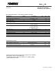
Thermal Characteristics
Characteristics Symbol
Max.
Units
Thermal Resistance, Junction to Case
DC Operation
R
ΘJ-C
Per Module, both conducting
Per Junction, both conducting
0.085
0.17
°C/W
°C/W
Thermal Resistance, Case to Sink Lubricated
R
ΘC-S
Per Module 0.05 °C/W
Information presented is based upon manufacturers testing and projected capabilities.
This information is subject to change without notice.
The manufacturer makes no claim as to the suitability of use, reliability, capability,
or future availability of this product.