
User Manual


www.vishay.com For technical questions, contact: ind-modules@vishay.com
Document Number: 94352
4 Revision: 29-Apr-08
90-110MT.KPbF Series
Vishay High Power Products
Three Phase Bridge
(Power Modules), 90/110 A
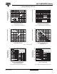
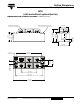
Fig. 6 - Current Ratings Characteristics Fig. 7 - Forward Voltage Drop Characteristics
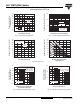
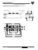
Fig. 8 - Total Power Loss Characteristics
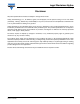
Fig. 9 - Maximum Non-Repetitive Surge Current Fig. 10 - Maximum Non-Repetitive Surge Current
100
110
120
130
140
150
90
80
70
60
50
Maximum Allowable Case
Temperature (°C)
Total Output Current (A)
20 40 60 80 100
160140120
0
120°
(Rect)
110MT..K Series
+
-
~
1
100
10
1000
Instantaneous Forward Current (A)
Instantaneous Forward Voltage (V)
123 450
T
J
= 25 °C
T
J
= 150 °C
110MT..K Series
Per junction
0
350
400
450
300
250
200
150
100
50
Maximum Total Power Loss (W)
Total Output Current (A)
25 50 75 100 125
150
0
120°
(Rect)
110MT..K Series
T
J
= 150 °C
0
350
400
450
300
250
200
150
100
50
Maximum Total Power Loss (W)
Maximum Allowable Ambient
Temperature (°C)
25 50 75 100
150125
0
R
thSA
= 0.05 K/W - ΔR
0.12 K/W
0.2 K/W
0.3 K/W
0.4 K/W
0.5 K/W
0.7 K/W
1.0 K/W
1.5 K/W
700
800
900
600
500
400
300
200
Peak Half Sine Wave
Forward Current (A)
Number of Equal Amplitude Half
Cycle Current Pulses (N)
10 1001
110MT..K Series
at 60 Hz 0.0083 s
at 50 Hz 0.0100 s
At any rated load condition and with
rated V
RRM
applied following surge.
Initial T
J
= 150 °C
1
100
10
1000
Peak Half Sine Wave
Forward Current (A)
Pulse Train Duration (s)
0.2 0.4 0.6 0.8 1.0
1.2
0
110MT..K Series
Initial T
J
= 150 °C
No voltage reapplied
Rated V
RRM
reapplied
versus pulse train duration.
Maximum non-repetitive surge current