
User Manual


Document Number: 94352 For technical questions, contact: ind-modules@vishay.com
www.vishay.com
Revision: 29-Apr-08 3
90-110MT.KPbF Series
Three Phase Bridge
(Power Modules), 90/110 A
Vishay High Power Products
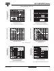
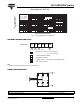
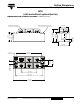
Fig. 1 - Current Ratings Characteristics Fig. 2 - Forward Voltage Drop Characteristics
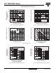
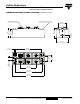
Fig. 3 - Total Power Loss Characteristics
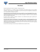
Fig. 4 - Maximum Non-Repetitive Surge Current Fig. 5 - Maximum Non-Repetitive Surge Current
130
140
150
120
110
100
90
80
70
60
50
Maximum Allowable Case
Temperature (°C)
Total Output Current (A)
25 50 75 100
125
0
120°
(Rect)
90MT..K Series
+
-
~
1
100
10
1000
Instantaneous Forward Current (A)
Instantaneous Forward Voltage (V)
123 4
5
0
T
J
= 25 °C
90MT..K Series
Per junction
T
J
= 150 °C
350
400
300
250
200
150
100
50
0
Maximum Total Power Loss (W)
Total Output Current (A)
20 40 60 80 100
120
0
120°
(Rect)
90MT..K Series
T
J
= 150 °C
300
350
400
250
200
150
100
50
0
Maximum Total Power Loss (W)
Maximum Allowable Ambient
Temperature (°C)
25 50 75 100 125
150
0
R
thSA
= 0.05 K/W - ΔR
0.12 K/W
0.2 K/W
0.3 K/W
0.05 K/W
0.7 K/W
1.0 K/W
1.5 K/W
550
600
650
700
500
450
400
350
300
250
200
Peak Half Sine Wave
Forward Current (A)
Number of Equal Amplitude Half
Cycle Current Pulses (N)
10
100
1
90MT..K Series
at 60 Hz 0.0083 s
at 50 Hz 0.0100 s
At any rated load condition and with
rated V
RRM
applied following surge.
Initial T
J
= 150 °C
600
650
700
750
800
550
500
450
400
350
300
250
200
150
Peal Half Sine Wave
Forward Current (A)
Pulse Train Duration (s)
0.1 1.00.01
Maximum non-repetitive surge current
90MT..K Series
Initial T
J
= 150 °C
No voltage reapplied
Rated V
RRM
reapplied
versus pulse train duration.