
User Manual


Document Number: 94262 For technical questions, contact: diodes-tech@vishay.com
www.vishay.com
Revision: 29-Aug-08 1
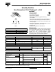
Schottky Rectifier
New Generation 3 D-61 Package, 2 x 40 A
88CNQ060APbF
Vishay High Power Products
FEATURES
• 150 °C T
J
operation
• Center tap module
• Low forward voltage drop
• High frequency operation
• Guard ring for enhanced ruggedness and long
term reliability
• High purity, high temperature epoxy encapsulation for
enhanced mechanical strength and moisture resistance
• New fully transfer-mold low profile, small footprint, high
current package
• Through-hole versions are currently available for use in
lead (Pb)-free applications (“PbF” suffix)
• Lead (Pb)-free
• Designed and qualified for industrial level
DESCRIPTION
The center tap Schottky rectifier module has been optimized
for very low forward voltage drop with moderate leakage.
The proprietary barrier technology allows for reliable
operation up to 150 °C junction temperature. Typical
applications are in switching power supplies, converters,
freewheeling diodes, and reverse battery protection.
PRODUCT SUMMARY
I
F(AV)
2 x 40 A
V
R
60 V
I
RM
240 mA at 125 °C
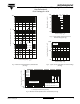
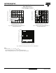
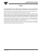
Base
common
cathode
Common
cathode
Anode
2
Anode
1
12
3
D-61-8
Available
RoHS*
COMPLIANT
MAJOR RATINGS AND CHARACTERISTICS
SYMBOL CHARACTERISTICS VALUES UNITS
I
F(AV)
Rectangular waveform 80 A
V
RRM
60 V
I
FSM
t
p
= 5 µs sine 5000 A
V
F
40 Apk, T
J
= 125 °C (per leg) 0.56 V
T
J
Range - 55 to 150 °C
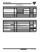
VOLTAGE RATINGS
PARAMETER SYMBOL 88CNQ060APbF UNITS
Maximum DC reverse voltage V
R
60 V
Maximum working peak reverse voltage V
RWM
ABSOLUTE MAXIMUM RATINGS
PARAMETER SYMBOL TEST CONDITIONS VALUES UNITS
Maximum average
forward current
See fig. 5
per leg
I
F(AV)
50 % duty cycle at T
C
= 120 °C, rectangular waveform, rated V
R
40
A
per device 80
Maximum peak one cycle
non-repetitive surge current per leg
See fig. 7
I
FSM
5 µs sine or 3 µs rect. pulse
Following any rated load
condition and with rated
V
R
applied
5000
10 ms sine or 6 ms rect. pulse 600
Non-repetitive avalanche energy per leg E
AS
T
J
= 25 °C, I
AS
= 1 A, L = 0.57 mH 75 mJ
Repetitive avalanche current per leg I
AR
Current decaying linearly to zero in 1 µs
Frequency limited by T
J
maximum V
A
= 1.5 x V
R
typical
1.0 A
* Pb containing terminations are not RoHS compliant, exemptions may apply