6121 Baker Road, Suite 108 Minnetonka, MN 55345 Phone (952) 933-6190 Fax (952) 933-6223 1-800-274-4284 www.chtechnology.com Thank you for downloading this document from C&H Technology, Inc. Please contact the C&H Technology team for the following questions - Technical Application Assembly Availability Pricing Phone – 1-800-274-4284 E-Mail – sales@chtechnology.com www.chtechnology.com - SPECIALISTS IN POWER ELECTRONIC COMPONENTS AND ASSEMBLIES - www.chtechnology.
80RIA...PbF, 81RIA...PbF, 82RIA...
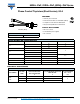
80RIA...PbF, 81RIA...PbF, 82RIA...PbF Series Vishay Semiconductors Phase Control Thyristors (Stud Version), 80 A ABSOLUTE MAXIMUM RATINGS PARAMETER SYMBOL Maximum average on-state current at case temperature Maximum RMS on-state current IT(AV) IT(RMS) TEST CONDITIONS 180° conduction, half sine wave DC at 75 °C case temperature t = 10 ms Maximum peak, one-cycle non-repetitive surge current ITSM t = 8.3 ms t = 10 ms t = 8.3 ms t = 10 ms Maximum I2t for fusing I2t t = 8.
80RIA...PbF, 81RIA...PbF, 82RIA...
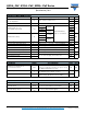
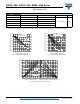
80RIA...PbF, 81RIA...PbF, 82RIA...PbF Series Phase Control Thyristors (Stud Version), 80 A Vishay Semiconductors RthJC CONDUCTION CONDUCTION ANGLE SINUSOIDAL CONDUCTION RECTANGULAR CONDUCTION 180° 0.042 0.030 120° 0.050 0.052 90° 0.064 0.070 60° 0.095 0.100 30° 0.164 0.165 TEST CONDITIONS UNITS TJ = TJ maximum K/W Maximum Allowable Case Temperature (°C) 130 80RIA Series RthJC (DC) = 0.
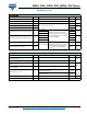
80RIA...PbF, 81RIA...PbF, 82RIA...PbF Series Maximum Average On-state Power Loss (W) Phase Control Thyristors (Stud Version), 80 A Vishay Semiconductors 180 DC 180° 120° 90° 60° 30° 160 140 120 R th SA 100 80 = 0. 6K /W 0. 4 K/ W -D e lt a 1K /W 1.
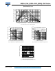
80RIA...PbF, 81RIA...PbF, 82RIA...PbF Series Phase Control Thyristors (Stud Version), 80 A 1 Steady State Value R thJC = 0.30 K/W Transient Thermal Impedance Z thJC (K/ W) Vishay Semiconductors (DC Operation) 0.1 0.01 80RIA Series 0.001 0.0001 0.001 0.01 0.1 1 10 Sq uare Wave Pulse Duration (s) Fig. 8 - Thermal Impedance ZthJC Characteristics Rectangular gate pulse a) Recommended load line for rated di/dt : 20V, 30ohms; tr<=0.
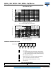
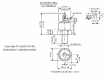
Outline Dimensions Vishay Semiconductors TO-209AC (TO-94) for 80RIA Series DIMENSIONS in millimeters (inches) Glass metal seal 37 )M IN . 2.5 (0.10) MAX. 16.5 (0.65) MAX. (0. Ø 8.5 (0.33) 9 .5 Ø 4.3 (0.17) Flexible lead 20 (0.79) MIN. C.S. 16 mm2 (0.025 s.i.) C.S. 0.4 mm2 Red silicon rubber (0.0006 s.i.) Red cathode 157 (6.18) 170 (6.69) White gate 215 ± 10 (8.46 ± 0.39) Fast-on terminals Red shrink 55 (2.17) MIN. White shrink AMP. 280000-1 REF-250 Ø 23.5 (0.92) MAX. 24 (0.94) MAX.
Legal Disclaimer Notice www.vishay.com Vishay Disclaimer ALL PRODUCT, PRODUCT SPECIFICATIONS AND DATA ARE SUBJECT TO CHANGE WITHOUT NOTICE TO IMPROVE RELIABILITY, FUNCTION OR DESIGN OR OTHERWISE. Vishay Intertechnology, Inc., its affiliates, agents, and employees, and all persons acting on its or their behalf (collectively, “Vishay”), disclaim any and all liability for any errors, inaccuracies or incompleteness contained in any datasheet or in any other disclosure relating to any product.