
User Manual


Document Number: 94347 For technical questions, contact: diodes-tech@vishay.com
www.vishay.com
Revision: 06-Jun-08 3
80EPS..PbF High Voltage Series
Input Rectifier Diode, 80 A
Vishay High Power Products
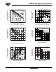
Fig. 1 - Current Rating Characteristics
Fig. 2 - Current Rating Characteristics
Fig. 3 - Forward Power Loss Characteristics
Fig. 4 - Forward Power Loss Characteristics
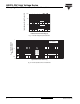
Fig. 5 - Maximum Non-Repetitive Surge Current
Fig. 6 - Maximum Non-Repetitive Surge Current
100
110
120
130
140
150
90
80
Maximum Allowable Case
Temperture (°C)
Average Forward Current (A)
8070605040302010
90
0
30°
60°
90°
120°
180°
80EPS.. Series
R
thJC
(DC) = 0.35 K/W
Conduction angle
Ø
140
150
130
120
110
100
90
Maximum Allowable Case
Temperature (°C)
Average Forward Current (A)
14012010080604020
0
DC
30°
60°
90°
120°
180°
80EPS.. Series
R
thJC
(DC) = 0.35 K/W
Ø
Conduction period
0
80
60
40
20
100
120
Maximum Average Forward
Power Loss (W)
Average Forward Current (A)
2010 3040
80
90
50 60 70
0
RMS limit
180°
120°
90°
60°
30°
80EPS.. Series
T
J
= 150 °C
Conduction angle
Ø
0
80
60
40
20
100
120
140
160
Maximum Average Forward
Power Loss (W)
Average Forward Current (A)
20 40
120
140
60 80 100
0
DC
180°
120°
90°
60°
30°
RMS limit
80EPS.. Series
T
J
= 150 °C
Ø
Conduction period
800
600
400
1600
1400
1200
1000
Peak Half Sine Wave
Forward Current (A)
Number of Equal Amplitudr Halfe
Cycle Current Pulse (N)
10 1001
At any rated load condition and with
rated V
RRM
applied following surge.
Initial T
J
= 150 °C
at 60 Hz 0.0083 s
at 50 Hz 0.0100 s
80EPS.. Series
800
600
400
1800
1600
1400
1200
1000
Peak Half Sine Wave
Forward Current (A)
Pulse Train Duration (s)
0.1
1
0.01
80EPS.. Series
Maximum non-repetitive surge current
versus pulse train duration.
Initial T
J
= 150 °C
No voltage reapplied
Rated V
RRM
reapplied