
Owner manual

Document Number: 94469 For technical questions, contact: ind-modules@vishay.com
www.vishay.com
Revision: 06-May-08 3
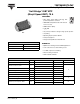
70MT060WHTAPbF
"Half-Bridge" IGBT MTP
(Warp2 Speed IGBT), 70 A
Vishay High Power Products
Note
(1)
T
0
, T
1
are thermistor´s temperatures
(2)
, temperature in Kelvin
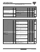
THERMISTOR SPECIFICATIONS
PARAMETER SYMBOL TEST CONDITIONS MIN. TYP. MAX. UNITS
Resistance R
0
(1)
T
0
= 25 °C - 30 - kΩ
Sensitivity index of the
thermistor material
β
(1)(2)
T
0
= 25 °C
T
1
= 85 °C
- 4000 - K
R
0
R
1
-------
β
1
T
0
------
1
T
1
------
–
⎝⎠
⎛⎞
exp=
DIODE SPECIFICATIONS (T
J
= 25 °C unless otherwise specified)
PARAMETER SYMBOL TEST CONDITIONS MIN. TYP. MAX. UNITS
Diode forward voltage drop V
FM
I
C
= 70 A, V
GE
= 0 V - 1.64 2.1
VI
C
= 140 A, V
GE
= 0 V - 2.1 2.4
I
C
= 70 A, V
GE
= 0 V, T
J
= 150 °C - 1.69 1.9
Diode reverse recovery time t
rr
V
CC
= 200 V, I
C
= 70 A
dI/dt = 200 A/µs
- 96 126 ns
Diode peak reverse current I
rr
- 9.4 12.8 A
Diode recovery charge Q
rr
- 440 750 nC
Diode reverse recovery time t
rr
V
CC
= 200 V, I
C
= 70 A
dI/dt = 200 A/µs
T
J
= 125 °C
- 140 194 ns
Diode peak reverse current I
rr
-1419A
Diode recovery charge Q
rr
- 950 1700 nC
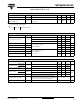
THERMAL - MECHANICAL SPECIFICATIONS
PARAMETER SYMBOL TEST CONDITIONS MIN. TYP. MAX. UNITS
Operating junction
temperature range
IGBT, Diode
T
J
- 40 - 150
°CThermistor - 40 - 125
Storage temperature range T
Stg
- 40 - 125
Junction to case
IGBT
R
thJC
- - 0.36
°C/WDiode --0.8
Case-to-sink Module R
thCS
Heatsink compound thermal conductivity = 1 W/mK - 0.06 -
Mounting torque to heatsink
A mounting compound is recommended and the
torque should be checked after 3 hours to allow for the
spread of the compound. Lubricated threads.
3 ± 10 % Nm
Weight 66 g