6121 Baker Road, Suite 108 Minnetonka, MN 55345 Phone (952) 933-6190 Fax (952) 933-6223 1-800-274-4284 www.chtechnology.com Thank you for downloading this document from C&H Technology, Inc. Please contact the C&H Technology team for the following questions - Technical Application Assembly Availability Pricing Phone – 1-800-274-4284 E-Mail – sales@chtechnology.com www.chtechnology.com - SPECIALISTS IN POWER ELECTRONIC COMPONENTS AND ASSEMBLIES - www.chtechnology.
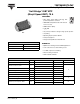
70MT060WHTAPbF Vishay High Power Products "Half-Bridge" IGBT MTP (Warp2 Speed IGBT), 70 A FEATURES • NPT warp2 speed IGBT technology with positive temperature coefficient RoHS • HEXFRED® antiparallel diodes with ultrasoft reverse recovery COMPLIANT • SMD thermistor (NTC) • Al2O3 BDC • Very low stay inductance design for high speed operation MTP • UL pending • Operating frequency 60 to 150 kHz • Totally lead (Pb)-free • Designed and qualified for industrial level PRODUCT SUMMARY VCES 600 V VCE(on) t
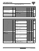
70MT060WHTAPbF Vishay High Power Products "Half-Bridge" IGBT MTP (Warp2 Speed IGBT), 70 A ELECTRICAL SPECIFICATIONS (TJ = 25 °C unless otherwise specified) PARAMETER SYMBOL Collector to emitter breakdown voltage V(BR)CES Collector to emitter voltage Gate threshold voltage Collector to emitter leaking current Gate to emitter leakage current VCE(on) VGE(th) ICES IGES MIN. TYP. MAX. UNITS VGE = 0 V, IC = 500 µA TEST CONDITIONS 600 - - V VGE = 15 V, IC = 70 A - 2.1 2.
70MT060WHTAPbF "Half-Bridge" IGBT MTP Vishay High Power Products (Warp2 Speed IGBT), 70 A THERMISTOR SPECIFICATIONS PARAMETER MIN. TYP. MAX. UNITS Resistance SYMBOL R0 (1) T0 = 25 °C TEST CONDITIONS - 30 - kΩ Sensitivity index of the thermistor material β (1)(2) T0 = 25 °C T1 = 85 °C - 4000 - K MIN. TYP. MAX. UNITS IC = 70 A, VGE = 0 V - 1.64 2.1 IC = 140 A, VGE = 0 V - 2.1 2.4 IC = 70 A, VGE = 0 V, TJ = 150 °C - 1.69 1.9 - 96 126 ns - 9.4 12.
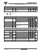
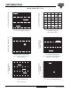
70MT060WHTAPbF Vishay High Power Products "Half-Bridge" IGBT MTP 16 VGE - Gate to Emitter Voltage (V) 1000 VGE = 15 V 100 TJ = 150 °C 10 TJ = 25 °C 14 12 10 8 6 4 Vcc = 480 V 2 0 1 0.0 1.0 2.0 3.0 4.0 0 5.0 200 400 600 800 VCE - Collector to Emitter Voltage (V) OG - Total Gate Charge (nC) Fig. 1 - Typical Output Characteristics Fig. 4 - Typical Gate Charge vs.
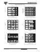
70MT060WHTAPbF "Half-Bridge" IGBT MTP Vishay High Power Products (Warp2 Speed IGBT), 70 A 350 4.5 VGEth (V) IC - Collector to Emitter Current (mA) 300 4.0 25 °C 3.5 125 °C 3.0 2.5 250 200 150 100 50 0 0.1 1.0 0 100 200 400 500 600 700 IC (mA) IC - Collector to Emitter Voltage (V) Fig. 7 - Typical Gate Threshold Voltage Fig.
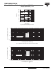
0MT060WHTAPbF Vishay High Power Products "Half-Bridge" IGBT MTP (Warp2 Speed IGBT), 70 A 2000 1800 VR = 200 V 1600 IF = 70 A, 125 °C QRR (nC) 1400 1200 1000 800 IF = 70 A, 25 °C 600 400 200 100 1000 dIF/dt - (A/µs) ZthJC - Thermal Impedance (°C/W) Fig. 13 - Typical Stored Charge vs. dIF/dt 1 0.1 0.01 0.001 0.00001 D = 0.75 D = 0.50 D = 0.33 D = 0.25 D = 0.20 Single Pulse (Thermal Resistance) 0.0001 0.01 0.001 1.0 0.
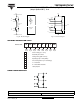
70MT060WHTAPbF "Half-Bridge" IGBT MTP Vishay High Power Products (Warp2 Speed IGBT), 70 A 3, 4 3, 4 2 T 10 Ω 11 11 12 10 Ω 12 R 5, 6 1 5, 6 10 Ω 9 Thermistor option 9 10 10 Ω 10 7, 8 7, 8 Fig. 16 - Electrical Diagram Fig.
Legal Disclaimer Notice Vishay Disclaimer All product specifications and data are subject to change without notice. Vishay Intertechnology, Inc., its affiliates, agents, and employees, and all persons acting on its or their behalf (collectively, “Vishay”), disclaim any and all liability for any errors, inaccuracies or incompleteness contained herein or in any other disclosure relating to any product.