
Owner manual


www.vishay.com For technical questions, contact: diodes-tech@vishay.com
Document Number: 94535
4 Revision: 07-Oct-08
63CPT100
Vishay High Power Products
High Performance
Schottky Generation 5.0,
2 x 30 A
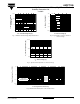
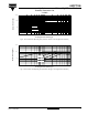
Fig. 5 - Maximum Allowable Case Temperature vs.
Average Forward Current
Fig. 6 - Forward Power Loss Characteristics
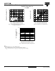
Fig. 7 - Maximum Non-Repetitive Surge Current
Note
(1)
Formula used: T
C
= T
J
- (Pd + Pd
REV
) x R
thJC
;
Pd = Forward power loss = I
F(AV)
x V
FM
at (I
F(AV)
/D) (see fig. 6);
Pd
REV
= Inverse power loss = V
R1
x I
R
(1 - D); I
R
at V
R1
= 80 % rated V
R
0 5 10 15 20 25 30 35 40 45
Allowable Case Temperature (°C)
I
F(AV)
- Average Forward Current (A)
145
150
155
160
165
170
175
180
see note (1)
Square wave (D = 0.50)
80 % rated V
r
applied
DC
0 5 10 15 20 25 30 35 40 45
Average Power Loss (W)
I
F(AV)
- Average Forward Current (A)
0
5
10
15
20
25
30
RMS limit
DC
180°
120°
90°
60°
30°
Square Wave Pulse Duration - t
p
(µs)
I
FSM
- Non-Repetitive Surge
Current (A)
10 100 1000 10 000
100
1000
10 000