6121 Baker Road, Suite 108 Minnetonka, MN 55345 Phone (952) 933-6190 Fax (952) 933-6223 1-800-274-4284 www.chtechnology.com Thank you for downloading this document from C&H Technology, Inc. Please contact the C&H Technology team for the following questions - Technical Application Assembly Availability Pricing Phone – 1-800-274-4284 E-Mail – sales@chtechnology.com www.chtechnology.com - SPECIALISTS IN POWER ELECTRONIC COMPONENTS AND ASSEMBLIES - www.chtechnology.
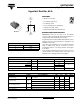
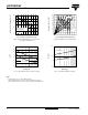
60CPH03PbF Vishay High Power Products Hyperfast Rectifier, 60 A FEATURES Base common cathode • Ultrafast recovery time • Low forward voltage drop 2 RoHS • Low leakage current COMPLIANT • 175 °C operating junction temperature • Lead (Pb)-free (“PbF” suffix) • Designed and qualified for industrial level TO-247AC 1 3 Anode Anode 2 1 2 Common cathode DESCRIPTIONS/APPLICATIONS 60CPH03PbF series are the state of the art ultrafast recovery rectifiers designed with optimized performance of forward voltage
60CPH03PbF Vishay High Power Products Hyperfast Rectifier, 60 A DYNAMIC RECOVERY CHARACTERISTICS (TJ = 25 °C unless otherwise specified) PARAMETER SYMBOL TEST CONDITIONS MIN. TYP. MAX. - - 55 TJ = 25 °C - 39 - TJ = 125 °C - 57 - IF = 1.0 A, dIF/dt = 50 A/µs, VR = 30 V Reverse recovery time Peak recovery current trr IRRM TJ = 25 °C TJ = 125 °C IF = 30 A dIF/dt = - 200 A/µs VR = 200 V - 2.8 - - 7.5 - UNITS ns A TJ = 25 °C - 55 - TJ = 125 °C - 214 - MIN. TYP. MAX.
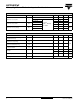
60CPH03PbF Hyperfast Rectifier, 60 A Vishay High Power Products 1000 1000 IR - Reverse Current (µA) IF - Instantaneous Forward Current (A) TJ = 175 °C 100 TJ = 175 °C TJ = 125 °C 10 TJ = 25 °C 1 0.2 100 TJ = 150 °C 10 TJ = 125 °C TJ = 100 °C 1 0.1 TJ = 25 °C 0.01 0.4 0.6 0.8 1.0 1.2 1.4 1.6 0 1.8 50 100 150 200 250 300 VF - Forward Voltage Drop (V) VR - Reverse Voltage (V) Fig. 1 - Typical Forward Voltage Drop Characteristics Fig. 2 - Typical Values of Reverse Current vs.
60CPH03PbF Vishay High Power Products Hyperfast Rectifier, 60 A 50 45 Average Power Loss (W) Allowable Case Temperature (°C) 180 160 DC 140 Square wave (D = 0.50) Rated VR applied RMS limit 40 35 30 D = 0.01 D = 0.02 D = 0.05 D = 0.10 D = 0.20 D = 0.50 DC 25 20 15 10 5 See note (1) 120 0 0 5 10 15 20 25 30 35 40 45 0 5 10 15 20 25 30 35 40 45 50 IF(AV) - Average Forward Current (A) IF(AV) - Average Forward Current (A) Fig. 5 - Maximum Allowable Case Temperature vs.
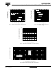
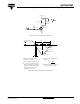
0CPH03PbF Hyperfast Rectifier, 60 A Vishay High Power Products VR = 200 V 0.01 Ω L = 70 µH D.U.T. dIF/dt adjust D IRFP250 G S Fig. 9 - Reverse Recovery Parameter Test Circuit (3) trr IF ta tb 0 Qrr (2) IRRM (4) 0.5 IRRM dI(rec)M/dt (5) 0.75 IRRM (1) dIF/dt (1) dIF/dt - rate of change of current through zero crossing (2) IRRM - peak reverse recovery current (3) trr - reverse recovery time measured from zero crossing point of negative going IF to point where a line passing through 0.
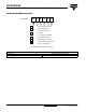
60CPH03PbF Vishay High Power Products Hyperfast Rectifier, 60 A ORDERING INFORMATION TABLE Device code 60 C P H 1 2 3 4 03 PbF 5 6 1 - Current rating (60 = 60 A) 2 - Circuit configuration: C = Common cathode 3 - Package: P = TO-247AC (modified) 4 - H = Hyperfast recovery 5 - Voltage code (03 = 300 V) 6 - None = Standard production PbF = Lead (Pb)-free Tube standard pack quantity: 25 pieces LINKS TO RELATED DOCUMENTS Dimensions http://www.vishay.
Legal Disclaimer Notice Vishay Notice The products described herein were acquired by Vishay Intertechnology, Inc., as part of its acquisition of International Rectifier’s Power Control Systems (PCS) business, which closed in April 2007. Specifications of the products displayed herein are pending review by Vishay and are subject to the terms and conditions shown below. Specifications of the products displayed herein are subject to change without notice. Vishay Intertechnology, Inc.