6121 Baker Road, Suite 108 Minnetonka, MN 55345 Phone (952) 933-6190 Fax (952) 933-6223 1-800-274-4284 www.chtechnology.com Thank you for downloading this document from C&H Technology, Inc. Please contact the C&H Technology team for the following questions Technical ● Application ● Assembly ● Availability ● Pricing Phone – 1-800-274-4284 E-Mail – sales@chtechnology.com www.chtechnology.com - SPECIALISTS IN POWER ELECTRONIC COMPONENTS AND ASSEMBLIES - www.chtechnology.
50RIA Series Vishay High Power Products Medium Power Thyristors (Stud Version), 50 A FEATURES • High current rating RoHS • Excellent dynamic characteristics COMPLIANT • dV/dt = 1000 V/µs option • Superior surge capabilities • Standard package • Metric threads version available • Types up to 1200 V VDRM/VRRM TO-208AC (TO-65) • RoHS compliant TYPICAL APPLICATIONS • Phase control applications in converters PRODUCT SUMMARY • Lighting circuits IT(AV) 50 A • Battery charges • Regulated power supplies
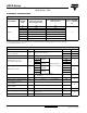
50RIA Series Vishay High Power Products Medium Power Thyristors (Stud Version), 50 A ELECTRICAL SPECIFICATIONS VOLTAGE RATINGS TYPE NUMBER VOLTAGE CODE VDRM/VRRM, MAXIMUM REPETITIVE PEAK AND OFF-STATE VOLTAGE (1) V VRSM, MAXIMUM NON-REPETITIVE PEAK VOLTAGE (2) V 10 100 150 20 200 300 40 400 500 60 600 700 80 800 900 100 1000 1100 120 1200 1300 50RIA IDRM/IRRM MAXIMUM AT TJ = TJ MAXIMUM mA 15 Notes (1) Units may be broken over non-repetitively in the off-state direction without da
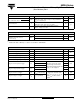
50RIA Series Medium Power Thyristors Vishay High Power Products (Stud Version), 50 A SWITCHING PARAMETER Maximum rate of rise of turned-on current SYMBOL VDRM ≤ 600 V VDRM ≤ 1600 V dI/dt TEST CONDITIONS TC = 125 °C, VDM = Rated VDRM, Gate pulse = 20 V, 15 Ω, tp = 6 µs, tr = 0.1 µs maximum ITM = (2 x rated dI/dt) A VALUES UNITS 200 A/µs 100 Typical delay time td TC = 25 °C, VDM = Rated VDRM, ITM = 10 A dc resistive circuit Gate pulse = 10 V, 15 Ω source, tp = 20 µs 0.
0RIA Series Vishay High Power Products Medium Power Thyristors (Stud Version), 50 A THERMAL AND MECHANICAL SPECIFICATIONS PARAMETER SYMBOL Maximum operating junction and storage temperature range TEST CONDITIONS TJ, TStg Maximum thermal resistance, junction to case RthJC Maximum thermal resistance, case to heatsink RthCS VALUES UNITS - 40 to 125 °C DC operation 0.35 K/W Mounting surface, smooth, flat and greased 0.25 Non-lubricated threads 3.4 + 0 - 10 % (30) Lubricated threads 2.
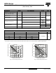
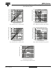
50RIA Series 80 1300 180° 120° 90° 60° 30° 70 60 Peak Half Sine Wave On-state Current (A) Maximum Average On-state Power Loss (W) Medium Power Thyristors Vishay High Power Products (Stud Version), 50 A 50 RMS Limit 40 30 Conduction Angle 20 50RIA Series TJ = 125°C 10 0 0 10 20 30 40 At Any Rated Load Condition And With Rated V RRM Applied Following Surge. Initial TJ = 125°C 1100 @ 60 Hz 0.0083 s @ 50 Hz 0.
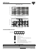
50RIA Series Vishay High Power Products Medium Power Thyristors Transient Thermal Impedance ZthJ-hs (K/W) (Stud Version), 50 A 1 Steady State Value RthJ-hs = 0.35 K/W 0.1 50RIA Series 0.01 0.001 0.01 0.1 1 10 Square Wave Pulse Duration (s) Fig. 8 - Thermal Impedance ZthJC Characteristics Rectangular gate pulse a) Recommended load line for rated di/dt : 20V, 30 ohms; tr<=0.5 µs b) Recommended load line for <=30% rated di/dt : 20V, 65 ohms tr<=1 µs 10 (b) (a) Tj=125 °C 1 VGD IGD 0.1 0.
Legal Disclaimer Notice Vishay Disclaimer ALL PRODUCT, PRODUCT SPECIFICATIONS AND DATA ARE SUBJECT TO CHANGE WITHOUT NOTICE TO IMPROVE RELIABILITY, FUNCTION OR DESIGN OR OTHERWISE. Vishay Intertechnology, Inc., its affiliates, agents, and employees, and all persons acting on its or their behalf (collectively, “Vishay”), disclaim any and all liability for any errors, inaccuracies or incompleteness contained in any datasheet or in any other disclosure relating to any product.