
Manual

Document Number: 94343 For technical questions, contact: diodes-tech@vishay.com
www.vishay.com
Revision: 06-Jun-08 3
40EPS..PbF High Voltage Series
Input Rectifier Diode, 40 A
Vishay High Power Products
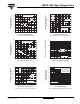
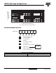
Fig. 1 - Current Rating Characteristics
Fig. 2 - Current Rating Characteristics
Fig. 3 - Forward Power Loss Characteristics
Fig. 4 - Forward Power Loss Characteristics
Fig. 5 - Forward Voltage Drop Chacteristics
Fig. 6 - Maximum Non-Repetitive Surge Current
95
135
140
145
150
130
125
120
115
110
105
100
Maximum Allowable Case
Temperature (°C)
Average Forward Current (A)
45403530252015105
0
30°
60°
90°
120°
180°
40EPS.. Series
R
thJC
(DC) = 0.6 K/W
Conduction angle
Ø
130
140
150
120
110
100
Maximum Allowable Case
Temperture (°C)
Average Forward Current (A)
2010 30405060
70
0
DC
30°
60°
90°
120°
180°
40EPS.. Series
R
thJC
(DC) = 0.6 K/W
Ø
Conduction period
5
0
10
15
20
25
35
30
40
45
50
55
60
Maximum Average Forward
Power Loss (W)
V
FM
- Forward Voltage Drop (V)
5
40353025201510
0
RMS limit
180°
120°
90°
60°
30°
40EPS.. Series
T
J
= 150 °C
Conduction angle
Ø
40
30
50
60
70
80
20
10
0
Maximum Average Forward
Power Loss (W)
Average Forward Current (A)
70605040302010
0
DC
180°
120°
90°
60°
30°
RMS limit
40EPS.. Series
T
J
= 150°C
Ø
Conduction period
1
100
10
1000
Instantaneous Forward Current (A)
Instantaneous Forward Voltage (V)
0.5 2.0 2.51.51.0
3.0
0
T
J
= 25 °C
T
J
= 150 °C
40EPS.. Series
400
450
500
350
300
250
200
150
100
Peak Half Sine Wave
Forward Current (A)
Pulse Train Duration (S)
0.1 1.0
0.01
Maximum non-repetitive surge current
40EPS.. Series
Initial T
J
= 150 °C
No voltage reapplied
Rated V
RRM
reapplied
versus pulse train duration.