
Instruction Manual

www.vishay.com For technical questions, contact: ind-modules@vishay.com
Document Number: 94206
2 Revision: 29-Apr-08
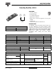
403CNQ100PbF
Vishay High Power Products
Schottky Rectifier, 400 A
Note
(1)
Pulse width < 300 µs, duty cycle < 2 %
ELECTRICAL SPECIFICATIONS
PARAMETER SYMBOL TEST CONDITIONS VALUES UNITS
Maximum forward voltage drop per leg
See fig. 1
V
FM
(1)
200 A
T
J
= 25 °C
0.84
V
400 A 1.07
200 A
T
J
= T
J
maximum
0.69
400 A 0.82
Maximum reverse leakage current per leg
See fig. 2
I
RM
(1)
T
J
= 25 °C
V
R
= Rated V
R
6
mA
T
J
= 125 °C 80
Maximum junction capacitance per leg C
T
V
R
= 5 V
DC
(test signal range 100 kHz to 1 MHz) 25 °C 5500 pF
Typical series inductance per leg L
S
From top of terminal hole to mounting plane 5.0 nH
Maximum voltage rate of change dV/dt Rated V
R
10 000 V/µs
THERMAL - MECHANICAL SPECIFICATIONS
PARAMETER SYMBOL MIN. TYP. MAX. UNITS
Maximum junction and storage temperature range T
J
, T
Stg
- 55 - 175 °C
Thermal resistance, junction to case per leg
R
thJC
- - 0.19
°C/WThermal resistance, junction to case per module - - 0.095
Thermal resistance, case to heatsink R
thCS
-0.10-
Weight
-68- g
-2.4-oz.
Mounting torque 35.4 (4) 53.1 (6)
lbf ⋅ in
(N ⋅ m)
Mounting torque center hole 30 (3.4) 40 (4.6)
Terminal torque 30 (3.4) - 44.2 (5)
Vertical pull - - 80
lbf ⋅ in
2" lever pull - - 35