6121 Baker Road, Suite 108 Minnetonka, MN 55345 Phone (952) 933-6190 Fax (952) 933-6223 1-800-274-4284 www.chtechnology.com Thank you for downloading this document from C&H Technology, Inc. Please contact the C&H Technology team for the following questions - Technical Application Assembly Availability Pricing Phone – 1-800-274-4284 E-Mail – sales@chtechnology.com www.chtechnology.com - SPECIALISTS IN POWER ELECTRONIC COMPONENTS AND ASSEMBLIES - www.chtechnology.
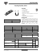
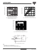
403CNQ100PbF Vishay High Power Products Schottky Rectifier, 400 A FEATURES • 175 °C TJ operation Lug terminal anode 1 Lug terminal anode 2 • Center tap module • Low forward voltage drop • High frequency operation • Guard ring for enhanced ruggedness and long term reliability TO-244 Base common cathode • Lead (Pb)-free • Designed and qualified for industrial level DESCRIPTION The 403CNQ... center tap Schottky rectifier module series has been optimized for low reverse leakage at high temperature.
403CNQ100PbF Vishay High Power Products Schottky Rectifier, 400 A ELECTRICAL SPECIFICATIONS PARAMETER SYMBOL TEST CONDITIONS 200 A Maximum forward voltage drop per leg See fig. 1 VFM (1) 200 A IRM (1) Maximum junction capacitance per leg CT Typical series inductance per leg LS Maximum voltage rate of change dV/dt 1.07 0.82 6 VR = Rated VR TJ = 125 °C V 0.69 TJ = TJ maximum TJ = 25 °C UNITS 0.84 TJ = 25 °C 400 A 400 A Maximum reverse leakage current per leg See fig.
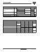
03CNQ100PbF Vishay High Power Products 1000 1000 TJ = 175 °C TJ = 175 °C IR - Reverse Current (mA) IF - Instantaneous Forward Current (A) Schottky Rectifier, 400 A TJ = 125 °C 100 TJ = 25 °C 10 TJ = 150 °C 100 TJ = 125 °C 10 TJ = 100 °C 1 TJ = 75 °C TJ = 50 °C 0.1 0.01 TJ = 25 °C 0.001 1 0 0.3 0.6 0.9 1.2 1.5 0 1.8 20 40 60 80 100 VR - Reverse Voltage (V) VFM - Forward Voltage Drop (V) Fig. 1 - Maximum Forward Voltage Drop Characteristics (Per Leg) Fig.
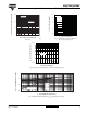
403CNQ100PbF 180 200 160 Average Power Loss (W) Allowable Case Temperature (°C) Vishay High Power Products Schottky Rectifier, 400 A DC Square wave (D = 0.50) 80 % rated Vr applied 140 120 100 150 D = 0.08 D = 0.17 D = 0.25 D = 0.33 D = 0.50 100 RMS limit DC 50 See note (1) 80 0 0 50 100 150 200 250 300 0 50 100 150 200 250 300 IF(AV) - Average Forward Current (A) Fig. 5 - Maximum Allowable Case Temperature vs. Average Forward Current (Per Leg) Fig.
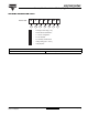
403CNQ100PbF Schottky Rectifier, 400 A Vishay High Power Products ORDERING INFORMATION TABLE Device code 40 3 C N Q 1 2 3 4 5 100 PbF 1 - Average current rating (x 10) 2 - Product silicon identification 3 - C = Circuit configuration 4 - N = Not isolated 5 - Q = Schottky rectifier diode 6 - Voltage rating (100 = 100 V) 7 - Lead (Pb)-free 6 7 LINKS TO RELATED DOCUMENTS Dimensions Document Number: 94206 Revision: 29-Apr-08 http://www.vishay.
Legal Disclaimer Notice Vishay Disclaimer All product specifications and data are subject to change without notice. Vishay Intertechnology, Inc., its affiliates, agents, and employees, and all persons acting on its or their behalf (collectively, “Vishay”), disclaim any and all liability for any errors, inaccuracies or incompleteness contained herein or in any other disclosure relating to any product.