6121 Baker Road, Suite 108 Minnetonka, MN 55345 Phone (952) 933-6190 Fax (952) 933-6223 1-800-274-4284 www.chtechnology.com Thank you for downloading this document from C&H Technology, Inc. Please contact the C&H Technology team for the following questions Technical ● Application ● Assembly ● Availability ● Pricing Phone – 1-800-274-4284 E-Mail – sales@chtechnology.com www.chtechnology.com - SPECIALISTS IN POWER ELECTRONIC COMPONENTS AND ASSEMBLIES - www.chtechnology.
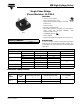
MB High Voltage Series Vishay High Power Products Single Phase Bridge (Power Modules), 25 A/35 A FEATURES • Universal, 3 way terminals: push-on, wrap around or solder • High thermal conductivity package, electrically insulated case RoHS COMPLIANT • Center hole fixing • Excellent power/volume ratio • Nickel plated terminals solderable using lead (Pb)-free solder; solder alloy Sn/Ag/Cu (SAC305); solder temperature 260 to 275 °C D-34 • UL E300359 approved • RoHS compliant • Designed and qualified for indus
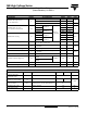
MB High Voltage Series Single Phase Bridge (Power Modules), 25 A/35 A Vishay High Power Products FORWARD CONDUCTION PARAMETER SYMBOL Maximum DC output current at case temperature IO 26MB-A 36MB-A Resistive or inductive load TEST CONDITIONS 25 35 Capacitive load 20 28 65 60 400 475 420 500 335 400 t = 10 ms Maximum peak, one cycle non-repetitive forward current IFSM t = 8.3 ms t = 10 ms t = 8.3 ms t = 10 ms Maximum I2t for fusing t = 8.3 ms I2t t = 10 ms t = 8.
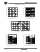
MB High Voltage Series 1000 Instantaneous Forward Current (A) 150 26MB..A Series 130 110 180° (Rect) 90 180° (Sine) 70 Tj = 150°C 100 0 5 10 15 20 25 Tj = 25°C 10 26MB..A Series 1 0.5 50 30 1 1.5 2 2.5 3 3.5 Average Forward Current (A) Instantaneous Forward Voltage (V) Fig. 1 - Current Ratings Characteristics Fig. 2 - Forward Voltage Drop Characteristics 50 26MB..
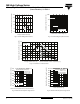
MB High Voltage Series Single Phase Bridge (Power Modules), 25 A/35 A 1000 Instantaneous Forward Current (A) 150 36MB..A Series 130 110 180° (Rect) 90 180° (Sine) 70 Tj = 150°C 100 10 0 5 10 15 20 25 30 35 Tj = 25°C 36MB..A Series 1 0.5 50 40 1 1.5 2 2.5 3 3.5 Average Forward Current (A) Instantaneous Forward Voltage (V) Fig. 6 - Current Ratings Characteristics Fig.
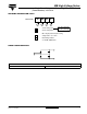
MB High Voltage Series Single Phase Bridge Vishay High Power Products (Power Modules), 25 A/35 A ORDERING INFORMATION TABLE Device code 36 MB 160 A 1 2 3 4 26 = 25 A (average) 36 = 35 A (average) 1 - Current rating code 2 - Circuit configuration: MB = Single phase european coding 3 - Voltage code x 10 = VRRM 4 - Diode bridge rectifier: A = 26 MB, 36MB series CIRCUIT CONFIGURATION + ~ - LINKS TO RELATED DOCUMENTS Dimensions Document Number: 93564 Revision: 17-Jun-08 http://www.
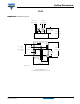
Outline Dimensions Vishay Semiconductors D-34 DIMENSIONS in millimeters (inches) 0.8 ± 0.05 (0.03 ± 0.002) 6.35 ± 0.1 (0.25 ± 0.004) 10.5 ± 0.15 (0.41 ± 0.006) 20.3 ± 0.15 (0.80 ± 0.006) - ~ 21.5 + 1.0 - 0.5 + 0.039 (0.85 ) - 0.020 28.5 ± 0.15 (1.12 ± 0.006) 9.5 ± 0.5 (0.37 ± 0.020) 12.7 ± 0.1 (0.5 ± 0.004) + ~ 5.25 ± 0.15 (0.21 ± 0.006) 12.7 ± 0.1 (0.5 ± 0.004) 28.5 ± 0.15 (1.12 ± 0.
Legal Disclaimer Notice www.vishay.com Vishay Disclaimer ALL PRODUCT, PRODUCT SPECIFICATIONS AND DATA ARE SUBJECT TO CHANGE WITHOUT NOTICE TO IMPROVE RELIABILITY, FUNCTION OR DESIGN OR OTHERWISE. Vishay Intertechnology, Inc., its affiliates, agents, and employees, and all persons acting on its or their behalf (collectively, “Vishay”), disclaim any and all liability for any errors, inaccuracies or incompleteness contained in any datasheet or in any other disclosure relating to any product.