
Instruction Manual

301U(R) Series
7
www.irf.com
Bulletin I2032 rev. B 03/03
20 40 60 80 100 120 140 160 180
Maximum Allowable Ambient Temperature (°C)
R
=
0
.
1
K
/
W
-
D
e
l
t
a
R
t
h
S
A
0
.
2
K
/
W
0
.
3
K
/
W
1
.
5
K
/
W
3
K
/
W
0
.
7
K
/
W
0
50
100
150
200
250
300
350
400
450
0 50 100 150 200 250 300
180°
120°
90°
60°
30°
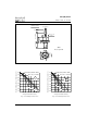
RM S Li m it
Conduction Angle
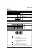
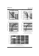
Maximum Average Forward Power Loss (W)
Average Forward Current (A)
T = 180°C
301U(R) Series (2500V)
J
Fig. 7 - Forward Power Loss Characteristics
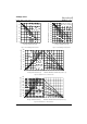
Fig. 8 - Forward Power Loss Characteristics
20 40 60 80 100 120 140 160 180
Maximum Allowable Ambient Temperature (°C)
R
=
0
.
1
K
/
W
-
D
e
l
ta
R
t
h
S
A
0
.
2
K
/
W
0
.
3
K
/
W
1
.
5
K
/
W
3
K
/
W
0
.
7
K
/
W
0
100
200
300
400
500
600
0
100 200 300 400 500
DC
180°
120°
90°
60°
30°
RMS Lim it
Conduction Period
Maximum Average Forward Power Loss (W)
Average Forward Current (A)
T = 180°C
301U(R) Series (2500V)
J
2000
3000
4000
5000
6000
7000
8000
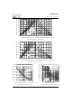
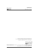
1 10 100
Number Of Equal Amplitude Half Cycle Current Pulses (N)
Peak Half Sine Wave Forward Current (A)
Initial T = 180°C
@ 60 Hz 0.0083 s
@ 50 Hz 0.0100 s
At Any Rated Load Condition And With
Rated V Applied Following Surge.
RRM
J
301U(R) Series
(1600V to 2000V)
Fig. 9 - Maximum Non-Repetitive Surge Current Fig. 10 - Maximum Non-Repetitive Surge Current
1000
2000
3000
4000
5000
6000
7000
8000
9000
0.01 0.1 1
Pulse Tra in Dura t io n (s)
Pe a k Ha lf Sine Wave Forward Current (A)
Versus Pulse Train Duration.
Initial T = 180 °C
No Voltage Reapplied
Rated V Reapplied
Maximum Non Repetitive Surge Current
RRM
J
301U(R) Series
(1600V to 2000V)