
Instruction Manual

301U(R) Series
6
www.irf.com
Bulletin I2032 rev. B 03/03
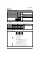
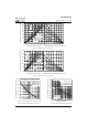
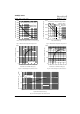
Fig. 5 - Forward Power Loss Characteristics
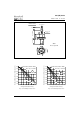
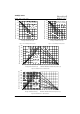
Fig. 3 - Current Ratings Characteristics Fig. 4 - Current Ratings Characteristics
110
120
130
140
150
160
170
180
0 50 100 150 200 250 300 350
30°
60°
90°
120°
180°
Average Forward Current (A)
Conduction Angle
Maximum Allowable Case Temperature (°C)
301U(R) Series (2500V)
R (DC) = 0.14 K/W
thJC
90
100
110
120
130
140
150
160
170
180
0 100 200 300 400 500
30°
60°
90°
180°
DC
120°
Average Forward Current (A)
Conduction Period
Maximum Allowable Case Temperature (°C)
301U(R) Series (2500V)
R (DC) = 0.14 K/ W
thJC
Fig. 6 - Forward Power Loss Characteristics
20 40 60 80 100 120 140 160 180
Maximum Allowable Ambient Temperature (°C)
R
=
0
.
1
K
/
W
-
D
e
l
t
a
R
t
h
S
A
0.
2
K/ W
0
.
3
K
/
W
1
.
5
K
/
W
3
K
/
W
0
.
7
K
/
W
0
50
100
150
200
250
300
350
400
0 50 100 150 200 250 300 350
180°
120°
90°
60°
30°
RM S Lim it
Conduction Angle
Maximum Average Forward Power Loss (W)
Average Forward Current (A)
301U(R) Series
(1600V to 2000V)
T = 180°C
J
20 40 60 80 100 120 140 160 180
Maximum Allowable Ambient Temperature (°C)
R
=
0
.
1
K
/
W
-
D
e
l
t
a
R
t
h
S
A
0
.
2
K
/
W
0
.
3
K
/
W
1
.
5
K
/
W
3
K
/
W
0
.
7
K
/
W
0
50
100
150
200
250
300
350
400
450
500
550
0
100 200 300 400 500 600
DC
180°
120°
90°
60°
30°
RM S Lim it
Conduction Period
Maximum Average Forward Power Loss (W)
Average Forward Current (A)
301U(R) Series
(1600V to 2000V)
T = 180°C
J