
Owner's manual


Document Number: 93507 For technical questions, contact: ind-modules@vishay.com
www.vishay.com
Revision: 02-Jun-08 3
300HF..L Series
Standard Recovery Diodes
(Stud Version), 300 A
Vishay High Power Products
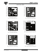
Fig. 1 - Current Ratings Characteristics
Fig. 2 - Current Ratings Characteristics
Fig. 3 - Forward Power Loss Characteristics
Fig. 4 - Forward Power Loss Characteristics
Fig. 5 - Maximum Non-Repetitive Surge Current
Fig. 6 - Maximum Non-Repetitive Surge Current
Average Forward Current (A)
Maximum Allowable Case Temperature (°C)
80
90
100
110
120
130
140
150
160
170
180
0 50 100 150 200 250 300 350 40
0
30°
60°
90°
120°
180°
Conduction Angle
RthJC (DC) = 0.17 K/W
300HF...L
Average Forward Current (A)
Maximum Allowable Case Temperature (°C)
80
90
100
110
120
130
140
150
160
170
180
0 100 200 300 400 50
0
30
°
60
°
90
°
180
°
DC
120
°
Conduction Period
RthJC (DC) = 0.17 K/W
300HF...L
Average Forward Current (A)
Maximum Average Forward Power Loss (W)
0
50
100
150
200
250
300
350
400
450
0 50 100 150 200 250 300 35
0
180°
120°
90°
60°
30°
RMS Limit
Conduction Angle
300HF...L
Tj = 180°C
Average Forward Current (A)
Maximum Average Forward Power Loss (W)
0
50
100
150
200
250
300
350
400
450
0 50 100 150 200 250 300 35
0
180
°
120
°
90
°
60
°
30
°
RMS Limit
Conduction Angle
300HF...L
Tj = 180
°
C
Number Of Equal Amplitude Half Cycle Current Pulses (N)
Peak Half Sine Wave Forward Current (A)
1500
2000
2500
3000
3500
4000
4500
5000
5500
11010
0
300HF...L
Initial Tj = 180
°
C
@ 60 Hz 0.0083 s
@ 50 Hz 0.0100 s
At Any Rated Load Condition And With
Rated Vrrm Applied Following Surge.
Pulse Train Duration(s)
Peak Half Sine Wave On-state Current (A)
500
1000
1500
2000
2500
3000
3500
4000
4500
5000
5500
6000
0.01 0.1 1 10
300HF...L
Initial Tj = 180
°
C
No Voltage Reapplied
Rated Vrrm Reapplied
Maximum Non Repetitive Surge Current
Versus Pulse Train Duration.