
Instruction Manual


www.vishay.com For technical questions, contact: ind-modules@vishay.com
Document Number: 93700
4 Revision: 19-Sep-08
22RIA Series
Vishay High Power Products
Medium Power Thyristors
(Stud Version), 22 A
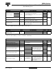
Note
• The table above shows the increment of thermal resistance R
thJC
when devices operate at different conduction angles than DC
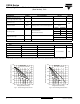
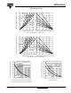
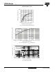
Fig. 1 - Current Ratings Characteristics Fig. 2 - Current Ratings Characteristics
THERMAL AND MECHANICAL SPECIFICATIONS
PARAMETER SYMBOL TEST CONDITIONS VALUES UNITS
Maximum operating junction
and storage temperature range
T
J
, T
Stg
- 65 to 125 °C
Maximum thermal resistance,
junction to case
R
thJC
DC operation 0.86
K/W
Maximum thermal resistance,
case to heatsink
R
thCS
Mounting surface, smooth, flat and greased 0.35
TO NUT TO DEVICE
Mounting torque
Lubricated threads
(Non-lubricated threads)
20 (27.5) 25 lbf ⋅ in
0.23 (0.32) 0.29 kgf · m
2.3 (3.1) 2.8 N · m
Approximate weight
14 g
0.49 oz.
Case style See dimensions - link at the end of datasheet TO-208AA (TO-48)
ΔR
thJC
CONDUCTION
CONDUCTION ANGLE SINUSOIDAL CONDUCTION RECTANGULAR CONDUCTION TEST CONDITIONS UNITS
180°
0.21 0.15
T
J
= T
J
maximum K/W
120°
0.25 0.25
90°
0.31 0.34
60°
0.45 0.47
30°
0.76 0.76
80
90
100
110
120
130
0 5 10 15 20 25
30°
60°
90°
120°
180°
Average On-state Current (A)
Maximum Allowabl e Case Temperature (°C)
Conduction Angle
22RIA Series
R (DC) = 0.86 K/W
thJC
80
90
100
110
120
130
0 10203040
DC
30°
60°
90°
120°
180°
Average On-state Current (A)
Maximum Allowable Case Temperature (°C)
Conduction Period
22RIA Series
R (DC) = 0.86 K/W
thJC