
User Manual

Document Number: 93223 For technical questions, contact: indmodules@vishay.com
www.vishay.com
Revision: 29-Apr-10 3
20MT060KF
"Full Bridge" IGBT MTP
(Ultrafast NPT IGBT), 20 A
Vishay High Power Products
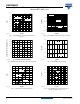
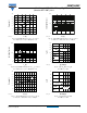
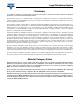
Fig. 1 - Maximum DC IGBT Collector Current vs. Case Temperature Fig. 2 - IGBT Reverse BIAS SOA
T
J
= 150 °C; V
GE
= 15 V
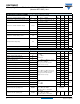
RECOVERY SPECIFICATIONS (T
J
= 25 °C unless otherwise specified)
PARAMETER SYMBOL TEST CONDITIONS MIN. TYP. MAX. UNITS
Diode reverse recovery time t
rr
I
F
= 20 A
dI/dt = 200 A/μs
V
R
= 400 V
- 85 106 ns
Diode peak reverse current I
rr
-4.56 A
Diode recovery charge Q
rr
- 188 318 nC
Diode reverse recovery time t
rr
I
F
= 20 A
dI/dt = 200 A/μs, V
R
= 400 V
T
J
= 125 °C
- 132 156 ns
Diode peak reverse current I
rr
-9.511A
Diode recovery charge Q
rr
- 626 842 nC
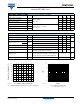
THERMAL AND MECHANICAL SPECIFICATIONS
PARAMETER SYMBOL TEST CONDITIONS MIN. TYP. MAX. UNITS
Operating junction temperature range T
J
- 40 - 150
°C
Storage temperature range T
Stg
- 40 - 125
Junction to case
IGBT
R
thJC
--1.1
°C/WDiode - - 2.1
Case to sink per module R
thCS
-0.06-
Clearance External shortest distance in air between 2 terminals 5.5 - -
mm
Creepage
Shortest distance along external surface of the
insulating material between 2 terminals
8--
Mounting torque
A mounting compound is recommended and the
torque should be checked after 3 hours to allow for
the spread of the compound. Lubricated threads.
3 ± 10 % Nm
Weight 66 g
Allowable Case Temperature (°C)
I
C
- Continuous Collector Current (A)
20151053025 35
40
0
80
120
140
160
0
40
60
100
20
DC
93223_01
I
C
(A)
V
CE
(V)
1 10 100 1000
0.01
0.1
1
93223_02
100
10