
User Manual


www.vishay.com For technical questions, contact: ind-modules@vishay.com
Document Number: 93493
2 Revision: 24-Jun-08
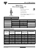
1N1...A, 1N36..A Series
Vishay High Power Products
Medium Power
Silicon Rectifier Diodes, 12 A
Notes
(1)
JEDEC registered values
(2)
I
2
t for time t
x
= I
2
√t x √t
x
(3)
Maximum peak reverse current (I
RM
) under same conditions ≈ 2 x rated I
R(AV)
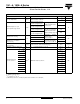
FORWARD CONDUCTION
PARAMETER SYMBOL TEST CONDITIONS VALUES UNITS
Maximum average forward current
at case temperature
I
F(AV)
180° sinusoidal conduction
12
(1)
A
150
(1)
°C
Maximum peak one cycle
non-repetitive surge current
I
FSM
Half cycle 50 Hz sine wave
or 6 ms rectangular pulse
Following any rated load
condition and with rated
V
RRM
applied
230
A
Half cycle 60 Hz sine wave
or 5 ms rectangular pulse
240
(1)
Half cycle 50 Hz sine wave
or 6 ms rectangular pulse
Following any rated load
condition and with V
RRM
applied following surge = 0
275
Half cycle 60 Hz sine wave
or 5 ms rectangular pulse
285
Maximum I
2
t for fusing
I
2
t
t = 10 ms
With rated V
RRM
applied
following surge,
initial T
J
= 200 °C
260
A
2
s
t = 8.3 ms 240
Maximum I
2
t for individual
device fusing
t = 10 ms
With V
RRM
= 0 following
surge, initial T
J
= 200 °C
370
t = 8.3 ms 340
Maximum I
2
√t for individual
device fusing
I
2
√t
(2)
t = 0.1 to 10 ms, V
RRM
= 0 following surge 3715 A
2
√s
Maximum forward voltage drop V
FM
I
F(AV)
= 12 A (38 A peak), T
C
= 25 °C 1.35
(1)
V
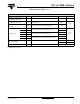
Maximum average
reverse current
V
RRM
= 50
I
R(AV)
(3)
Maximum rated I
F(AV)
and T
C
3.0
(1)
mA
V
RRM
= 100 2.5
(1)
V
RRM
= 150 2.25
(1)
V
RRM
= 200 2.0
(1)
V
RRM
= 300 1.75
(1)
V
RRM
= 400 1.5
(1)
V
RRM
= 500 1.25
(1)
V
RRM
= 600 1.0
(1)
V
RRM
= 700 0.9
(1)
V
RRM
= 800 0.8
(1)
V
RRM
= 900 0.7
(1)
V
RRM
= 1000 0.6
(1)