
User guide


www.vishay.com For technical questions, contact: ind-modules@vishay.com
Document Number: 93496
2 Revision: 24-Jun-08
1N3208 Series
Vishay High Power Products
Stud-Mounted
Silicon Rectifier Diodes, 15 A
Notes
(1)
JEDEC registered values
(2)
I
2
t for time t
x
= I
2
√t x √t
x
Note
(1)
JEDEC registered values
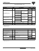
FORWARD CONDUCTION
PARAMETER SYMBOL TEST CONDITIONS VALUES UNITS
Maximum average forward current
at case temperature
I
F(AV)
180° sinusoidal conduction
15
(1)
A
150
(1)
°C
Maximum peak one cycle
non-repetitive surge current
I
FSM
Half cycle 50 Hz sine wave
or 6 ms rectangular pulse
Following any rated load
condition and with rated
V
RRM
applied
239
A
Half cycle 60 Hz sine wave
or 5 ms rectangular pulse
250
(1)
Half cycle 50 Hz sine wave
or 6 ms rectangular pulse
Following any rated load
condition and with V
RRM
applied following surge = 0
284
Half cycle 60 Hz sine wave
or 5 ms rectangular pulse
297
Maximum I
2
t for fusing
I
2
t
t = 10 ms
With rated V
RRM
applied
following surge,
initial T
J
= 150 °C
286
A
2
s
t = 8.3 ms 260
Maximum I
2
t for individual
device fusing
t = 10 ms
With V
RRM
= 0 following
surge, initial T
J
= 150 °C
403
t = 8.3 ms 368
Maximum I
2
√t for individual
device fusing
I
2
√t
(2)
t = 0.1 to 10 ms, V
RRM
= 0 following surge 3870 A
2
√s
Maximum forward voltage drop V
FM
I
F(AV)
= 15 A (47.1 A peak), T
C
= 150 °C 1.5
(1)
V
Maximum average reverse current I
R(AV)
Maximum rated I
F(AV)
and T
C
= 150 °C 10
(1)
mA
THERMAL AND MECHANICAL SPECIFICATIONS
PARAMETER SYMBOL TEST CONDITIONS VALUES UNITS
Maximum junction operating and
storage temperature range
T
J
, T
Stg
- 65 to 175
(1)
°C
Maximum internal thermal
resistance, junction to case
R
thJC
DC operation 0.65
°C/W
Thermal resistance,
case to sink
R
thCS
Mounting surface, smooth, flat and greased 0.25
Mounting torque
minimum
Non-lubricated threads
2.3 (20)
N · m
(lbf · in)
maximum 3.5 (30)
Weight
28.5 g
1oz.
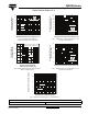
Case style JEDEC DO-203AB (DO-5)