
Owner's manual


www.vishay.com For technical questions, contact: ind-modules@vishay.com
Document Number: 93492
2 Revision: 02-Mar-09
1N1183, 1N3765, 1N1183A, 1N2128A Series
Vishay High Power Products
Power Silicon Rectifier Diodes,
35 A/40 A/60 A
Notes
(1)
JEDEC registered values
(2)
I
2
t for time t
x
= I
2
√t x √t
x
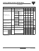
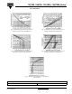
FORWARD CONDUCTION
PARAMETER SYMBOL TEST CONDITIONS 1N1183 1N3765 1N1183A 1N2128A UNITS
Maximum average forward current
at case temperature
I
F(AV)
1-phase operation,
180° sinusoidal conduction
35
(1)
35
(1)
40
(1)
60
(1)
A
140
(1)
140
(1)
150
(1)
140
(1)
°C
Maximum peak one cycle
non-repetitive surge current
I
FSM
Half cycle 50 Hz
sine wave or 6 ms
rectangular pulse
Following any
rated load
condition and
with rated
V
RRM
applied
480 380 765 860
A
Half cycle 60 Hz
sine wave or 5 ms
rectangular pulse
500
(1)
400
(1)
800
(1)
900
(1)
Half cycle 50 Hz
sine wave or 6 ms
rectangular pulse
Following any
rated load
condition and
with ½ V
RRM
applied following
surge = 0
570 455 910 1000
Half cycle 60 Hz
sine wave or 5 ms
rectangular pulse
595 475 950 1050
Maximum I
2
t for fusing
I
2
t
t = 10 ms
With rated V
RRM
applied following
surge, initial
T
J
= T
J
maximum
1140 730 2900 3700
A
2
s
t = 8.3 ms 1040 670 2650 3400
Maximum I
2
t for individual
device fusing
t = 10 ms
With V
RRM
= 0
following surge,
initial T
J
=
T
J
maximum
1610 1030 4150 5250
t = 8.3 ms 1470 940 3750 4750
Maximum I
2
√t for individual
device fusing
I
2
√t
(2)
t = 0.1 to 10 ms,
V
RRM
= 0 following surge
16 100 10 300 41 500 52 500 A
2
√s
Maximum peak forward voltage
at maximum forward current (I
FM
)
V
FM
T
J
= 25 °C
1.7
(1)
1.8
(1)
1.3
(1)
1.3
(1)
V
110 110 126 188 A
Maximum average
reverse current
V
RRM
= 700
I
R(AV)
Maximum rated I
F(AV)
and T
C
-5.0
(1)
--
mA
V
RRM
= 800 - 4.0
(1)
--
V
RRM
= 900 - 3.0
(1)
--
V
RRM
= 1000 - 2.0
(1)
--
Maximum rated I
F(AV)
, V
RRM
and T
C
10
(1)
-2.5
(1)
10
(1)