6121 Baker Road, Suite 108 Minnetonka, MN 55345 Phone (952) 933-6190 Fax (952) 933-6223 1-800-274-4284 www.chtechnology.com Thank you for downloading this document from C&H Technology, Inc. Please contact the C&H Technology team for the following questions Technical ● Application ● Assembly ● Availability ● Pricing Phone – 1-800-274-4284 E-Mail – sales@chtechnology.com www.chtechnology.com - SPECIALISTS IN POWER ELECTRONIC COMPONENTS AND ASSEMBLIES - www.chtechnology.
1N1183, 1N3765, 1N1183A, 1N2128A Series Vishay High Power Products Power Silicon Rectifier Diodes, 35 A/40 A/60 A DESCRIPTION/FEATURES • Low leakage current series • Good surge current capability up to 1000 A • Can be supplied to meet stringent military, aerospace and other high reliability requirements • RoHS compliant DO-203AB (DO-5) PRODUCT SUMMARY IF(AV) 35 A/40 A/60 A MAJOR RATINGS AND CHARACTERISTICS PARAMETER IF(AV) IFSM I2 t TEST CONDITIONS TC 1N3765 1N1183A 1N2128A 35 (1) 35 (1) 40 (1)
1N1183, 1N3765, 1N1183A, 1N2128A Series Vishay High Power Products Power Silicon Rectifier Diodes, 35 A/40 A/60 A FORWARD CONDUCTION PARAMETER SYMBOL Maximum average forward current at case temperature IF(AV) TEST CONDITIONS 1-phase operation, 180° sinusoidal conduction Half cycle 50 Hz sine wave or 6 ms rectangular pulse Maximum peak one cycle non-repetitive surge current IFSM Half cycle 60 Hz sine wave or 5 ms rectangular pulse Half cycle 50 Hz sine wave or 6 ms rectangular pulse Half cycle 60 Hz s
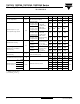
1N1183, 1N3765, 1N1183A, 1N2128A Series Power Silicon Rectifier Diodes, Vishay High Power Products 35 A/40 A/60 A THERMAL AND MECHANICAL SPECIFICATIONS PARAMETER SYMBOL TEST CONDITIONS 1N1183 1N3765 1N1183A 1N2128A Maximum operating case temperature range TC - 65 to 190 (1) - 65 to 200 Maximum storage temperature range TStg - 65 to 175 (1) - 65 to 200 Maximum internal thermal resistance, junction to case RthJC DC operation Thermal resistance, case to sink RthCS Mounting surface, smooth,
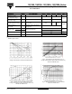
1N1183, 1N3765, 1N1183A, 1N2128A Series Vishay High Power Products Power Silicon Rectifier Diodes, 35 A/40 A/60 A Fig. 5 - Maximum Non-Repetitive Surge Current vs. Number of Current Pulses, 1N1183 and 1N3765 Series Fig. 8 - Maximum High Level Forward Power Loss vs. Average Forward Current, 1N1183A Series Fig. 6 - Average Forward Current vs. Maximum Allowable Case Temperature, 1N1183A Series Fig. 9 - Maximum Forward Voltage vs. Forward Current, 1N1183A Series Fig.
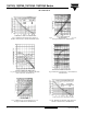
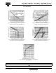
1N1183, 1N3765, 1N1183A, 1N2128A Series Power Silicon Rectifier Diodes, Vishay High Power Products 35 A/40 A/60 A Fig. 11 - Maximum Non-Repetitive Surge Current vs. Number of Current Pulses, 1N2128A Series Fig. 13 - Maximum Low Level Forward Power Loss vs. Average Forward Current, 1N2128A Series Fig. 12 - Maximum Allowable Case Temperature vs. Average Forward Current, 1N2128A Series Fig. 14 - Maximum High Level Forward Power Loss vs. Average Forward Current, 1N2128A Series Fig.
Legal Disclaimer Notice Vishay Disclaimer All product specifications and data are subject to change without notice. Vishay Intertechnology, Inc., its affiliates, agents, and employees, and all persons acting on its or their behalf (collectively, “Vishay”), disclaim any and all liability for any errors, inaccuracies or incompleteness contained herein or in any other disclosure relating to any product.