
Instruction Manual

Document Number: 28339 For technical questions, contact: aluminumcaps2@vishay.com
www.vishay.com
Revision: 08-Aug-08 53
198 PHR-SI
Aluminum Capacitors
Power High Ripple Current Snap-In
Vishay BCcomponents
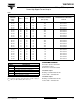
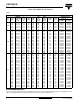
Table 3
RIPPLE CURRENT AND USEFUL LIFE
Note
Calculation example for case Ø D x L = 35 x 25 mm
Therefore the maximum ripple current multiplier at 70 °C, 300 Hz and 2 m/s air-flow = 1.57 x 1.17 x 1.35 = 2.48.
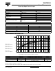
ADDITIONAL ELECTRICAL DATA
PARAMETER CONDITIONS VALUE
Voltag e
Surge voltage ≥ 400 V versions U
s
=1.1xU
R
Reverse voltage ≤ 1V
Current
Leakage current
After 1 minute at U
R
I
L1
≤ 0.006 C
R
xU
R
+4µA
After 5 minutes at U
R
I
L5
≤ 0.002 C
R
xU
R
+4µA
Inductance
Equivalent series inductance (ESL) All case sizes
typ. 19 nH
max. 25 nH
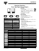
MULTIPLIER OF RIPPLE CURRENT (I
R
) AS A FUNCTION OF FREQUENCY
FREQUENCY (Hz)
I
R
MULTIPLIER
50 0.86
100 1.00
300 1.17
600 1.24
1000 1.29
≥ 10 000 1.40
MAXIMUM RIPPLE CURRENT MULTIPLIER
PARAMETER CONDITION MAXIMUM RIPPLE CURRENT MULTIPLIER VALUE
Ambient temperature (T
amb
)70°C from nomogram; see Fig.7 1.57
Operating frequency (f) 300 Hz from frequency table; see Table 1.17
Air-flow 2 m/s from air-flow; see Fig.6 1.35
1.0
1.1
1.2
1.3
1.4
1.5
1.6
0 0.5 1 1.5 2 2.5 3 3.5 4 4.5 5
(1)
(2)
(3)
(4)
air velocity (m/s)
I
R
forced
I
R
free
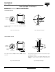
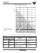
Fig. 6 Multiplier of ripple current (I
R
) as a function of air-flow
Curve 1: case
Ø DxL=35x25mm
Curve 2: case
Ø DxL=22x25mm
Curve 3: case
Ø DxL=35x50mm
Curve 4: case
Ø D x L = 22 x 40 mm