
Instruction Manual

198 PHR-SI
Vishay BCcomponents
Aluminum Capacitors
Power High Ripple Current Snap-In
www.vishay.com For technical questions, contact: aluminumcaps2@vishay.com
Document Number: 28339
50 Revision: 08-Aug-08
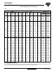
DIMENSIONS in millimeters AND AVAILABLE FORMS
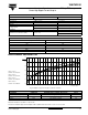
TWO TERMINAL SNAP-IN
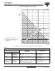
THREE TERMINAL SNAP-IN
+ TERMINAL
- TERMINAL
Ø D
L + 2
max.
L
Bottom view
5.8
+ 0
- 1
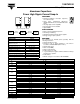
Fig. 2 Two terminal snap-in
The minus terminal can be marked with a black dot or with a
n
imprinted ‘-’ sign.
10
± 0.1
Ø 2 ± 0.1 (2 x)
Fig. 3 Mounting hole diagram
+ TERMINAL
- TERMINAL
Ø D
L + 2
max.
L
Bottom view
minus pole
marking
4 ± 0.5
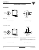
Fig. 4 Three terminal snap-in
The negative terminal has TWO pins which are BOTH electricall
y
connected.
10
± 0.1
3.3
± 0.1
4.75 ± 0.1
Ø 2 ± 0.1 (2 x)
Ø 2.5 ± 0.1
The 10 mm spacing of the 2 pin snap-in is used as the base layout
and a third hole is added.
The third hole is closer to the negative primary hole so that
polarization is always maintained, together with added mechanical
stability.
Fig. 5 Mounting hole diagram