
Owner's manual


www.vishay.com For technical questions, contact: aluminumcaps2@vishay.com Document Number: 28341
100 Revision: 14-Oct-08
159 PUL-SI
Vishay BCcomponents
Aluminum Capacitors
Power Ultra Long Life Snap-In
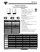
DIMENSIONS in millimeters AND AVAILABLE FORMS
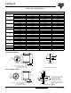
220
- 22 x 30 25 x 45 30 x 40
- 25 x 25 30 x 35 35 x 30
--35x30-
270
- 22 x 35 25 x 50 30 x 45
- 25 x 30 30 x 40 35 x 35
- 30 x 25 35 x 30 -
330
22 x 30 22 x 40 30 x 45 30 x 50
- 25 x 30 35 x 35 35 x 40
-30x25 - -
390
22 x 35 25 x 35 30 x 50 35 x 45
25 x 30 30 x 30 35 x 40 -
470
22 x 40 25 x 40 35 x 45 35 x 50
30 x 25 30 x 30 - -
35 x 25
560
- 25 x 45 - 35 x 60
25 x 35 30 x 35 - -
30 x 30 35 x 30 - -
680
25 x 45 30 x 40 35 x 60 -
30 x 30 35 x 35 - -
35 x 25 - - -
820
25 x 50 30 x 45 - -
30 x 35 35 x 35 - -
35 x 30 35 x 40 - -
1000
30 x 45 35 x 40 - -
35 x 35 35 x 45 - -
1200
30 x 50 35 x 45 - -
35 x 35 35 x 50 - -
1500 35 x 45 - - -
1800 35 x 50 - - -
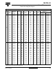
SELECTION CHART FOR C
R
, U
R
AND RELEVANT NOMINAL CASE SIZES (Ø D x L in mm)
C
R
(µF)
U
R
(V)
200 250 400 450
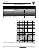
Ø D
L + 2 max.
L
Bottom view
5.8 mm
+ 0
- 1
+ Terminal
- Terminal
The minus terminal can be marked with a black dot
or with an imprinted ‘-’ sign.
Fig.2 Two terminal snap-in
Fig.3 Mounting hole diagram
10
±0.1
Ø 2 ± 0.1 (2 x)
Fi
g
.4 Two terminal sna
p
-in
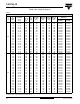
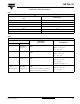
L
Bottom view
Minus pole
marking
Ø D
L + 2 max.
4 ± 0.5
+ Terminal
- Terminal
The negative terminal has TWO pins which are BOTH
electrcally connected
10
±0.1
3.3
± 0.1
4.75 ± 0.1
2.5 ± 0.1
2 ± 0.1 (2 x)
The 10 mm spacing of the 2 pin
snap-in is used as the base layout
and a third hole is added.
The third hole is closer to the
negative primary hole so that
polarization is always maintained,
together with added mechanical
stability.
Ø
Ø
Fig.5 Mounting hole diagram
TWO TERMINAL SNAP-IN
THREE TERMINAL SNAP-IN