
Owner's manual

Document Number: 28338 For technical questions, contact: aluminumcaps2@vishay.com
www.vishay.com
Revision: 18-Aug-08 43
157 PUM-SI
Aluminum Capacitors
Power Ultra Miniature Snap-In
Vishay BCcomponents
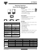
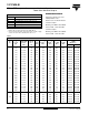
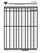
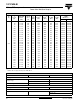
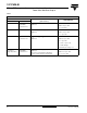
Table 1
THREE TERMINAL SNAP-IN
DIMENSIONS in millimeters, MASS AND PACKAGING QUANTITIES
NOMINAL
CASE SIZE
Ø D x L
Ø D
max.
L
max.
MASS
(g)
PACKAGING QUANTITIES
(units per box)
22 x 25 23 27 ≈ 12 100
22 x 30 23 32 ≈ 16 100
22 x 35 23 37 ≈ 20 100
22 x 40 23 42 ≈ 23 100
25 x 25 26 27 ≈ 20 100
25 x 30 26 32 ≈ 22 100
25 x 35 26 37 ≈ 24 100
25 x 40 26 42 ≈ 27 100
25 x 45 26 47 ≈ 32 100
25 x 50 26 52 ≈ 38 100
30 x 25 31 27 ≈ 25 100
30 x 30 31 32 ≈ 30 100
30 x 35 31 37 ≈ 35 100
30 x 40 31 42 ≈ 40 100
30 x 45 31 47 ≈ 45 100
30 x 50 31 52 ≈ 50 100
35 x 25 36 27 ≈ 33 50
35 x 30 36 32 ≈ 40 50
35 x 35 36 37 ≈ 48 50
35 x 40 36 42 ≈ 55 50
35 x 45 36 47 ≈ 63 50
35 x 50 36 52 ≈ 72 50
35 x 60 36 62 ≈ 82 50
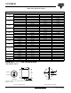
Ø D
L + 2 max.L
4 ± 0.5
+ TERMINAL
- TERMINAL
minus pole
marking
Bottom view
Fig.4 Three terminal snap-in
T
he negative terminal has TWO pins which are BOTH electrically
connected.
Ø 2 ± 0.1(2 x )
Ø 2.5 ± 0.1
10 ± 0.1
3.3 ± 0.1
4.75 ± 0.1
The 10 mm spacing of the 2 pin snap-in is used as the base layout
and a third hole is added.
The third hole is closer to the negative primary hole so that
polarization is always maintained, together with added mechanical
stability.
Fig.5 Mounting hole diagram