
Owner manual

Document Number: 93489 For technical questions, contact: ind-modules@vishay.com
www.vishay.com
Revision: 21-May-08 3
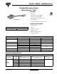
45L(R), 150K(R), 150KS(R) Series
Standard Recovery Diodes
(Stud Version), 150 A
Vishay High Power Products
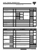
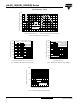
Note
• The table above shows the increment of thermal resistance R
thJC
when devices operate at different conduction angles than DC
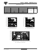
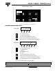
Fig. 1 - Current Ratings Characteristics Fig. 2 - Current Ratings Characteristics
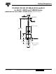
Fig. 3 - Forward Power Loss Characteristics
ΔR
thJC
CONDUCTION
CONDUCTION ANGLE SINUSOIDAL CONDUCTION RECTANGULAR CONDUCTION TEST CONDITIONS UNITS
180°
0.031 0.023
T
J
= T
J
maximum K/W
120°
0.038 0.040
90°
0.048 0.053
60°
0.071 0.075
30°
0.120 0.121
140
150
160
170
180
190
200
0 20406080100120140160
30°
60°
90°
120°
180°
Maximum Allowable Case Temperature (°C)
Conduction Angle
Average Forward Current (A)
45L...,150... Se ries
R (DC) = 0.25 K/ W
thJC
140
150
160
170
180
190
200
0 50 100 150 200 250
DC
30°
60°
90°
120°
180°
Maximum Allowable Case Temperature (°C)
Conduction Period
Average Forward Current (A)
45L..., 150... Series
R (DC) = 0.25 K/ W
thJC
25 50 75 100 125 150 175 200
Maximum Allowable Ambient Temperature (°C)
R
=
0
.
1
K
/
W
-
D
e
l
t
a
R
0
.
2
K
/
W
0.6
K
/
W
0
.
8
K
/
W
1
.
5
K
/
W
2
K
/
W
3
K
/
W
1
K
/
W
0
.
4
K
/
W
0
.
3
K
/
W
t
h
SA
160
0
20
40
60
80
100
120
140
160
180
0
40 80 120
RM S Lim it
180°
120°
90°
60°
30°
Conduction Angle
Maximum Average Forward Power Loss (W)
Average Forward Current (A)
45L..., 150... Series
T = 200°C
J