
Instruction Manual

Document Number: 93487 For technical questions, contact: ind-modules@vishay.com
www.vishay.com
Revision: 29-Sep-08 3
12F(R) Series
Standard Recovery Diodes
(Stud Version), 12 A
Vishay High Power Products
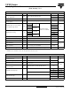
Note
• The table above shows the increment of thermal resistance R
thJC
when devices operate at different conduction angles than DC
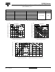
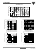
Fig. 1 - Current Ratings Characteristics Fig. 2 - Current Ratings Characteristics
Fig. 3 - Forward Power Loss Characteristics
ΔR
thJC
CONDUCTION
CONDUCTION ANGLE SINUSOIDAL CONDUCTION RECTANGULAR CONDUCTION TEST CONDITIONS UNITS
180° 0.33 0.26
T
J
= T
J
maximum K/W
120° 0.41 0.44
90° 0.53 0.58
60° 0.78 0.81
30° 1.28 1.29
140
150
160
170
180
0 2 4 6 8 101214
30°
60°
90°
120°
180°
Maximum Allowable Case Temperature (°C)
Conduction Angle
Average Forward Current (A)
12F(R) Series
R (DC) = 2.0 K/W
thJC
130
140
150
160
170
180
048121620
DC
30°
60°
90°
120°
180°
Maximum Allowable Case Temperature (°C)
Conduction Period
Average Forward Current (A)
12F(R) Series
R (DC) = 2.0 K/W
thJC
0255075100
Maximum Allowable Ambient Temperature (°C)
R
=
8
K
/
W
-
D
e
l
t
a
R
t
h
S
A
6
K
/
W
1
0
K
/
W
1
2
K
/
W
1
5
K
/
W
2
0
K
/
W
3
0
K
/
W
0
2
4
6
8
10
12
14
02468101214
Average Forward Current (A)
RMS Limit
Maximum Average Forward Power Loss (W)
Conduction Angle
180°
120°
90°
60°
30°
12F(R) Series
T = 175°C
J