
Owner's manual

www.vishay.com For technical questions, contact: diodes-tech@vishay.com
Document Number: 94126
2 Revision: 25-Jun-07
115CNQ015APbF
Vishay High Power Products
Schottky Rectifier
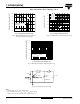
New Generation 3 D-61 Package, 110 A
Note
(1)
Pulse width < 300 µs, duty cycle < 2 %
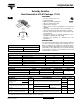
ELECTRICAL SPECIFICATIONS
PARAMETER SYMBOL TEST CONDITIONS VALUES UNITS
Maximum forward voltage drop per leg
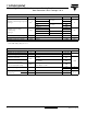
See fig. 1
V
FM
(1)
55 A
T
J
= 25 °C
0.37
V
110 A 0.46
55 A
T
J
= 75 °C
0.33
110 A 0.43
Maximum reverse leakage
current per leg
See fig. 2
I
RM
(1)
T
J
= 25 °C
V
R
= Rated V
R
20
mA
T
J
= 100 °C 1200
T
J
= 100 °C V
R
= 12 V 900
T
J
= 100 °C V
R
= 5 V 540
Maximum junction capacitance per leg C
T
V
R
= 5 V
DC
(test signal range 100 kHz to 1 MHz) 25 °C 5500 pF
Typical series inductance per leg L
S
Measured lead to lead 5 mm from package body 5.5 nH
Maximum voltage rate of change dV/dt Rated V
R
10 000 V/µs
THERMAL - MECHANICAL SPECIFICATIONS
PARAMETER SYMBOL TEST CONDITIONS VALUES UNITS
Maximum junction temperature range T
J
- 55 to 125
°C
Maximum storage temperature range T
Stg
- 55 to 150
Maximum thermal resistance,
junction to case per leg
R
thJC
DC operation
See fig. 4
0.5
°C/W
Maximum thermal resistance,
junction to case per package
DC operation 0.25
Typical thermal resistance,
case to heatsink (D-61-8 only)
R
thCS
Mounting surface, smooth and greased
Device flatness < 5 mils
0.30
Approximate weight
7.8 g
0.28 oz.
Mounting torque
(D-61-8 only)
minimum 40 (35)
kgf · cm
(lbf · in)
maximum 58 (50)