
Owner's manual

Document Number: 94126 For technical questions, contact: diodes-tech@vishay.com
www.vishay.com
Revision: 25-Jun-07 1
Schottky Rectifier
New Generation 3 D-61 Package, 110 A
115CNQ015APbF
Vishay High Power Products
FEATURES
• 125 °C T
J
operation (V
R
< 5 V)
• Center tap module
• Optimized for OR-ing applications
• Ultra low forward voltage drop
• High frequency operation
• Guard ring for enhanced ruggedness and long term
reliability
• High purity, high temperature epoxy encapsulation for
enhanced mechanical strength and moisture resistance
• New fully transfer-mold low profile, small footprint, high
current package
• Through-hole versions are currently available for use in
lead (Pb)-free applications (“PbF” suffix)
• Designed and qualified for industrial level and
lead (Pb)-free
DESCRIPTION
The center tap Schottky rectifier module has been optimized
for ultra low forward voltage drop specifically for the
OR-ing of parallel power supplies. The proprietary barrier
technology allows for reliable operation up to 125 °C junction
temperature. Typical applications are in parallel switching
power supplies, converters, reverse battery protection, and
redundant power subsystems.
PRODUCT SUMMARY
I
F(AV)
110 A
V
R
at T
J
= 100 °C 15 V
®
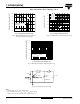
Base
common
cathode
Common
cathode
Anode
2
Anode
1
12
3
D-61-8
Available
RoHS*
COMPLIANT
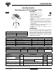
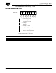
MAJOR RATINGS AND CHARACTERISTICS
SYMBOL CHARACTERISTICS VALUES UNITS
I
F(AV)
Rectangular waveform 110 A
V
RRM
15 V
I
FSM
t
p
= 5 µs sine 5050 A
V
F
55 Apk, T
J
= 75 °C (per leg) 0.33 V
T
J
Range - 55 to 125 °C
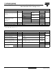
VOLTAGE RATINGS
PARAMETER SYMBOL TEST CONDITIONS 115CNQ015APbF UNITS
Maximum DC reverse voltage V
R
T
J
= 100 °C 15
V
Maximum working peak reverse voltage V
RWM
T
J
= 125 °C 5
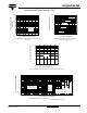
ABSOLUTE MAXIMUM RATINGS
PARAMETER SYMBOL TEST CONDITIONS VALUES UNITS
Maximum average
forward current
See fig. 5
per leg
I
F(AV)
50 % duty cycle at T
C
= 112 °C, rectangular waveform
55
A
per device 110
Maximum peak one cycle
non-repetitive surge current per leg
See fig. 7
I
FSM
5 µs sine or 3 µs rect. pulse
Following any rated load
condition and with rated
V
RRM
applied
5050
A
10 ms sine or 6 ms rect. pulse 830
Non-repetitive avalanche energy per leg E
AS
T
J
= 25 °C, I
AS
= 2 A, L = 4.5 mH 54 mJ
Repetitive avalanche current per leg I
AR
Current decaying linearly to zero in 1 µs
Frequency limited by T
J
maximum V
A
= 3 x V
R
typical
2A
* Pb containing terminations are not RoHS compliant, exemptions may apply