6121 Baker Road, Suite 108 Minnetonka, MN 55345 Phone (952) 933-6190 Fax (952) 933-6223 1-800-274-4284 www.chtechnology.com Thank you for downloading this document from C&H Technology, Inc. Please contact the C&H Technology team for the following questions - Technical Application Assembly Availability Pricing Phone – 1-800-274-4284 E-Mail – sales@chtechnology.com www.chtechnology.com - SPECIALISTS IN POWER ELECTRONIC COMPONENTS AND ASSEMBLIES - www.chtechnology.
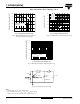
115CNQ015APbF Vishay High Power Products Schottky Rectifier New Generation 3 D-61 Package, 110 A FEATURES ® • • • • • • • Base common cathode 1 Anode 1 2 Common cathode • • 3 Anode 2 • D-61-8 125 °C TJ operation (VR < 5 V) Available Center tap module Optimized for OR-ing applications RoHS* COMPLIANT Ultra low forward voltage drop High frequency operation Guard ring for enhanced ruggedness and long term reliability High purity, high temperature epoxy encapsulation for enhanced mechanical strength
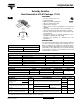
115CNQ015APbF Vishay High Power Products Schottky Rectifier New Generation 3 D-61 Package, 110 A ELECTRICAL SPECIFICATIONS PARAMETER SYMBOL TEST CONDITIONS 55 A Maximum forward voltage drop per leg See fig. 1 VFM (1) 110 A 55 A 110 A TJ = 25 °C Maximum reverse leakage current per leg See fig. 2 IRM (1) Maximum junction capacitance per leg CT Typical series inductance per leg LS Maximum voltage rate of change dV/dt TJ = 100 °C TJ = 25 °C TJ = 75 °C VR = Rated VR VALUES 0.37 0.46 0.
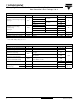
115CNQ015APbF Schottky Rectifier Vishay High Power Products New Generation 3 D-61 Package, 110 A 10 000 IR - Reverse Current (mA) IF - Instantaneous Forward Current (A) 1000 100 10 TJ = 125 °C TJ = 75 °C TJ = 25 °C TJ = 125 °C 1000 TJ = 100 °C TJ = 75 °C 100 TJ = 50 °C 10 1 TJ = 25 °C 1 0 0.2 0.4 0.6 0.8 1.0 1.2 0 1.4 2 4 6 8 10 12 14 16 VR - Reverse Voltage (V) VFM - Forward Voltage Drop (V) Fig. 1 - Maximum Forward Voltage Drop Characteristics (Per Leg) Fig.
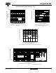
115CNQ015APbF Vishay High Power Products Schottky Rectifier New Generation 3 D-61 Package, 110 A 30 120 Average Power Loss (W) Allowable Case Temperature (°C) 125 DC 115 Square wave (D = 0.50) 5 V applied 110 105 D = 0.75 D = 0.50 D = 0.33 D = 0.25 D = 0.20 25 20 15 RMS limit 10 DC 5 See note (1) 0 100 0 10 20 30 40 50 60 70 80 0 90 10 20 30 40 50 60 70 80 IF(AV) - Average Forward Current (A) Fig. 5 - Maximum Allowable Case Temperature vs.
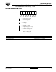
115CNQ015APbF Schottky Rectifier Vishay High Power Products New Generation 3 D-61 Package, 110 A ORDERING INFORMATION TABLE Device code 115 C N Q 015 A PbF 1 2 3 4 5 6 7 1 - Current rating (110 A) 2 - Circuit configuration 3 - Package C = Common cathode N = D-61 4 - Schottky “Q” series 5 - Voltage rating (015 = 15 V) 6 - A = D-61-8 package style 7 - None = Standard production PbF = Lead (Pb)-free Standard pack quantity: A = 10 pieces LINKS TO RELATED DOCUMENTS Dimensio
Legal Disclaimer Notice Vishay Notice The products described herein were acquired by Vishay Intertechnology, Inc., as part of its acquisition of International Rectifier’s Power Control Systems (PCS) business, which closed in April 2007. Specifications of the products displayed herein are pending review by Vishay and are subject to the terms and conditions shown below. Specifications of the products displayed herein are subject to change without notice. Vishay Intertechnology, Inc.