
Manual
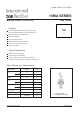

10RIA Series
Bulletin I2405 rev. B 04/06
I
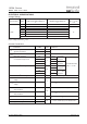
T(AV)
Max. average on-state current 10 A 180° conduction, half sine wave
@ Case temperature 85 °C
I
T(RMS)
Max. RMS on-state current 25 A
I
TSM
Max. peak, one-cycle 225 t = 10ms No voltage
non-repetitive surge current 240 t = 8.3ms reapplied
190 t = 10ms 100% V
RRM
200 t = 8.3ms reapplied Sinusoidal half wave,
I
2
t Maximum I
2
t for fusing 255 t = 10ms No voltage Initial T
J
= T
J
max.
233 t = 8.3ms reapplied
180 t = 10ms 100% V
RRM
165 t = 8.3ms reapplied
I
2
√t Maximum I
2
√t for fusing 2550 A
2
√s t = 0.1 to 10ms, no voltage reapplied
V
T(TO)1
Low level value of threshold 1.10 (16.7% x π x I
T(AV)
< I < π x I
T(AV)
), T
J
= T
J
max.
voltage
V
T(TO)
2
High level value of threshold 1.39 (I > π x I
T(AV)
), T
J
= T
J
max.
voltage
r
t1
Low level value of on-state 24.3 (16.7% x π x I
T(AV)
< I < π x I
T(AV)
), T
J
= T
J
max.
slope resistance
r
t2
High level value of on-state 16.7 (I > π x I
T(AV)
), T
J
= T
J
max.
slope resistance
V
TM
Max. on-state voltage 1.75 V I
pk
= 32A, T
J
= 25°C t
p
= 10ms sine pulse
I
H
Maximum holding current 130
I
L
Typical latching current 200
Parameter 10RIA Units Conditions
On-state Conduction
A
2
s
mΩ
V
A
mA
T
J
= 25°C, anode supply 12V resistive load
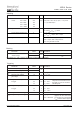
Voltage V
DRM
/V
RRM
, max. repetitive V
RSM
, maximum non- I
DRM
/I
RRM
max.
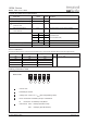
Type number Code peak and off-state voltage (1) repetitive peak voltage (2)
@ T
J
= T
J
max.
VVmA
10 100 150 20
20 200 300
40 400 500
60 600 700
10RIA 80 800 900 10
100 1000 1100
120 1200 1300
ELECTRICAL SPECIFICATIONS
Voltage Ratings
(1) Units may be broken over non-repetitively in the off-state direction without damage, if dI/dt does not exceed 20A/μs
(2) For voltage pulses with t
p
≤ 5ms
Document Number: 93689
www.vishay.com
2