
Owner's manual
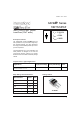

10ETS12PbF SAFEIR Series
Bulletin I2191 12/04
I
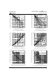
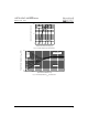
F(AV)
Max. Average Forward Current 10 A @ T
C
= 105° C, 180° conduction half sine wave
I
FSM
Max. Peak One Cycle Non-Repetitive 170 10ms Sine pulse, rated V
RRM
applied
Surge Current 200 10ms Sine pulse, no voltage reapplied
I
2
t Max. I
2
t for fusing 130 10ms Sine pulse, rated V
RRM
applied
145 10ms Sine pulse, no voltage reapplied
I
2
√t Max. I
2
√t for fusing 1450 A
2
√s t = 0.1 to 10ms, no voltage reapplied
Part Number
V
RRM
, maximum V
RSM
, maximum non repetitive I
RRM
peak reverse voltage peak reverse voltage 150°C
VVmA
10ETS12PbF 1200 1300 0.5
Voltage Ratings
T
J
Max. Junction Temperature Range - 40 to 150 °C
T
stg
Max. Storage Temperature Range - 40 to 150 °C
R
thJC
Max. Thermal Resistance Junction 2.5 °C/W DC operation
to Case
R
thJA
Max. Thermal Resistance Junction 62 °C/W
to Ambient (PCB Mount)*
T
s
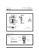
Soldering Temperature 240 °C
wt Approximate Weight 2 (0.07) g (oz.)
Case Style TO-220AC
Device Marking 10ETS12
Thermal-Mechanical Specifications
Parameters Values Units Conditions
Absolute Maximum Ratings
Electrical Specifications
Parameters Values Units Conditions
A
A
2
s
V
FM
Max. Forward Voltage Drop 1.1 V @ 10A, T
J
= 25°C
r
t
Forward slope resistance 20 mΩ
V
F(TO)
Threshold voltage 0.82 V
I
RM
Max. Reverse Leakage Current 0.05 T
J
= 25 °C
0.50 T
J
= 150 °C
Parameters Values Units Conditions
T
J
= 150°C
V
R
= rated V
RRM
mA
* When mounted on 1" square (650mm
2
) PCB of FR-4 or G-10 material 4 oz (140µm) copper 40°C/W
For recommended footprint and soldering techniques refer to application note #AN-994
Document Number: 94337
www.vishay.com
2